A Pipe rack is a structure designed and installed specifically to support multiple pipes, where an adequate building or structure is not available (mainly outside the building).
Pipe racks are necessary for arranging the process and utility pipelines throughout the plant. It connects all the equipment (installed at a different location) with lines that can not run through adjacent areas.
Pipe racks are also used in secondary ways, as it also carries the electrical wire, instrument wire, fire fighting systems, lights, etc. Air-cooled or fin-fan type heat exchangers are often supported above pipe racks to reduce the plant space requirements.
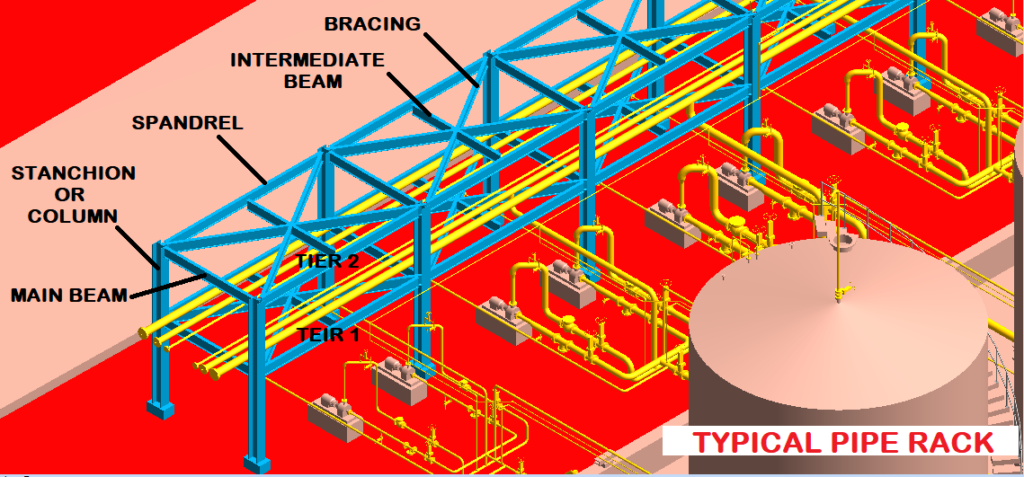
Table of Contents
Pipe Rack Type
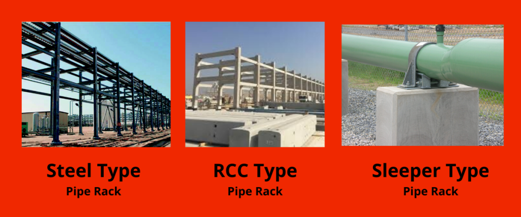
There are mainly three types of Pipe rack-
- Steel Structure Type
- RCC Structure Type
- Sleeper Type (This is also called Pipe Track)
Steel Structure Pipe Rack
A steel structure type pipe rack is preferred for lines up to 12″ or 300 MB.
RCC Structure Pipe Rack
An RRC structure-type pipe rack is preferred for lines above 12″ or 300 MB and up-to 30″ or 750 MB. It is also used if the pipe rack height is above 10 m.
Sleeper Type Pipe Rack or Pipe Track
Sleeper type pipe racks are mainly used for pipelines above 30″ or 750 MB.
The most commonly used shapes for racks are L/T/U/H/Z. The shapes are mainly decided based on space availability and optimized use of space and material.
Note: the above conditions are not fixed, it can slightly differ from company to company.
Documents Required for Pipe Rack Development
Pipe Rack Designing involves considerable planning and coordination with other engineering groups to deliver error-free work. Following documents or engineering deliverables are required-
- PFD (Process Flow Diagram)
- P&ID (Piping and Instrumentation Diagram)
- Line List
- Line Routing Diagram or GAD
- Over All Plot Plan
- Unit Plot Plan
- Equipment Layout
- Piping Material Specifications
- Client Specification
- Fire-Proofing Information
Who Designs What?
Pipe rack designing is not a one-man army job. It involves a lot of engineering calculations and so required contribution from the different engineering disciplines. Let’s see the below table
| Work Done | Prepared By | Submitted To |
|---|---|---|
| 1. Pipe rack width, height & length calculations 2. Calculation of Pipes and equipment loads on Pipe rack | Piping Engineer | Structure & Civil Engineer |
| 3. Size and Type of Member (Column and beam) selection as per different loads (like pipe & equipment load, cable tray load, wind load, seismic load, etc.) on pipe rack 4. Bracing selection | Structural Engineer | Civil & Piping Engineer |
| 5. Foundation Calculations | Civil Engineer | NA |
| 6. Electrical Cable tray calculations | Electrical Engineer | Structure & Civil Engineer |
| 7. Instrument cable tray calculations | Instrument Engineer | Structure & Civil Engineer |
| 8. Fire-proofing load | Fire Fighting Engineer | Structure & Civil Engineer |
Note: In this article, we are going to learn pipe rack width, height, and length calculations.
Before coming to the pipe rack width calculation, We must know the line placing criteria. If you don’t know how to place the pipes on the rack, you will not be able to get the accurate width of the pipe rack.
Do not worry, Line placing is not rocket science, I have described all the important points that need to be considered while placing the lines on the pipe rack-
Line Placing Criteria for Pipe Rack
Followings point are need to considered-
- Group the utility and process lines.
- Keep hot and cold lines away from each other to minimize the heat transfer.
- For ease of support to expansion loops, always try to keep the hotlines near to the stanchion or column.
- If the lines are heavy, keep those lines near to the stanchion or column to minimize the stress (bending moment) on the horizontal beam or member.
- Do not get confused that if the line size is greater the line will be heavier, no it’s not like that, as the gas-filled lines will create less stress on the horizontal beam than the liquid-filled lines.
- Once we can compromise with weight, but never ever compromise in case of temperature, always maintain enough space between the lines.
- We should avoid keeping a temperature-sensitive process line near high-temperature lines. For example, if the instrument-air line is placed near to the high-temperature line, it will absorb the temperature and can harm the instrument or instrument diaphragm.
- We should also avoid keeping the temperature-sensitive lines near to chilled lines, as the other line can absorb the moisture, and further, it can be problematic for that particular line.
- In the hydrocarbon and chemical industry, avoid keeping utility lines below the process line (means the process lines will be kept on the first tier and utility lines on the second tier. As in the case of leakage of the process fluid, water may get contaminated (as the water line is a utility line), and it can be harmful to the person.
- In the food and pharmaceutical industry, it is mandatory to keep utility lines below the process lines to maintain the purity of the product.
- If possible, keep the supply and return lines near each other, as these lines are having minimum temperature difference, and so heat transfer is less. Example: steam and condensate, cooling water supply, and chilled water supply and return.
- To balance the width of the pipe rack of different tiers, water, air, nitrogen such lines can be kept on any of the tiers, there is no restriction to such utility lines.
- Always try to keep future expansion in the middle of the beam, as it can help initially to reduce the stress in the beam.
- Future expansion shall be a minimum of 20 % of the total pipe rack width calculation, and maximum what else comes if space is not a problem.
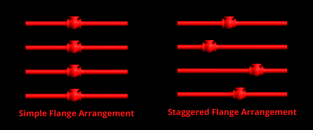
- Make sure that the flanges are staggered to minimize the pipe rack width
Pipe Rack Width Calculation
We will do a Case study for pipe width calculation so that we can better understand the above-discussed points. Let’s take a problem below-
Input required
| Line Size | Line Type | Flange Rating | Insulation Type | Insulation Thickness |
|---|---|---|---|---|
| 12″ | Process Line | 1500# | No Insulation | NA |
| 10″ | Process Line | 900# | Hot Insulation | 125 mm |
| 8″ | Process Line | 300# | No Insulation | NA |
| 6″ | Process Line | 600# | Hot Insulation | 75 mm |
| 4″ | Process Line | 2500# | Hot Insulation | 75 mm |
| 3″ | Process Line | 150# | No Insulation | NA |
Calculation Steps:
Step 1:
Place the line as per the line placing criteria-
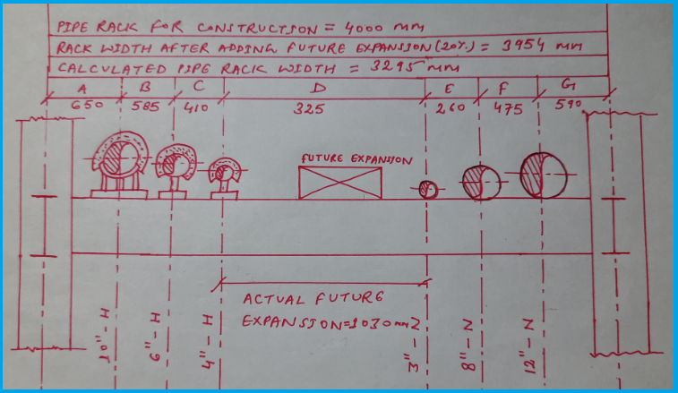
We placed the heavier pipes near the stanchion or column (12″ &10 ” pipe). Refer fig. 4
Hot and cold pipes are kept away from each other (as 10″, 6″ & 4″ lines are hot-line, we kept these lines at the left side, and others are on the right side. Refer fig. 4
Step 2:
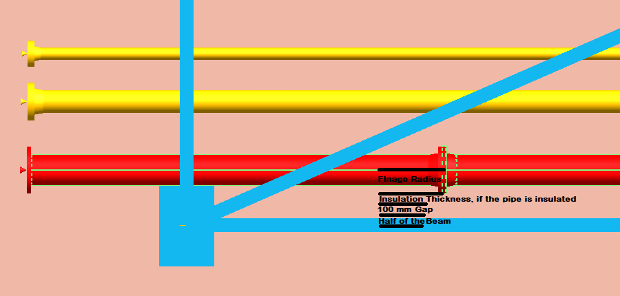
Calculate the distance A using the below formula-
Distance between structure (spandrel) to nearest pipe = (Haft of beam + Gap 100 mm + Insulation thickness + Flange radius)
Refer the below figure for better understanding of formula-
You can make a table as prepared below for ease of calculation
| Pipe NPS | Rating | Pipe Radius (ASME B 36.10 or 36.19) | Flange Radius (ASME B 16.5) |
|---|---|---|---|
| 3 | 150# | 44 | 95 |
| 4 | 2500# | 57 | 177 |
| 6 | 600# | 84 | 177 |
| 8 | 300# | 109 | 190 |
| 10 | 900# | 136 | 272 |
| 12 | 1500 | 161 | 337 |
So,
A = 150+100+125+272 = 647 = 650 mm
Note: We consider the beam size is 300 mm (This size is decided by structure or civil engineer)
Similarly,
Distance G can be calculated
G = 150+100+0+337 = 587 = 590 mm
Step 3:
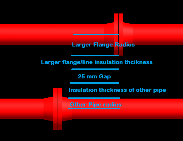
Calculate the pipe to pipe distance “B” using the below formula
Pipe to pipe distance = (Larger flange radius + larger pipe insulation thickness + 25 mm Gap + Insulation thickness of other pipe + another pipe radius)
Refer the below figure for better understanding of formula-
So,
B = 272+125+25+75+84 = 581 = 585 mm
Similarly,
C = 177+75+25+75+57 = 409 = 410 mm
D = 177+75+25+0+44 = 321 = 325 mm
E = 190+0+25+0+44 = 259 = 260 mm
F = 337+0+25+0+109 = 471 = 475 mm
Note: 1. We consider the minimum flange rating 300#, because the line may have an orifice meter, and the orifice meter required a flange of a minimum of Class 300 because Class 150 flange thickness is not enough for tapping.
Note: 2. If the pipe NPS is greater, it does not mean that the flange radius will also be greater. For example flange radius of two lines of 10″ & Class 600 and 10″ & Class 1500 will not be same, as the flange radius are 255 mm 292 mm respectively.
Step 4:
Add the distances A+B+C+D+E+F+G
Calculated pipe rack width = 650+585+410+325+260+475+590 = 3295 mm
Step 5:
Add 20 % future expansion to calculated pipe rack width
Pipe rack width after adding future expansion = (calculated width + 20 % future expansion) = 3295+659 = 3954 = 4000 mm
Note: Pipe rack width should be rounded to the next 500 mm, which means pipe rack will be multiple of 500 mm.
Step 6:
Now Find the actual future expansion distance by subtracting distance (A+B+C+E+F+G) from pipe rack width with future expansion
Actual future expansion = 4000- (650+585+410+260+475+590) = 1030 mm
All the calculated results are mentioned in the below fig. 7
Important Points for Pipe Rack Height
- Identify the largest process or the utility lines except for the flare line.
- Line sizes can be identified using a line list or P&ID.
- Rack height is calculated considering the largest line size of the process or the utility and the same size of the branch so that all the small branches can be accommodated in the gap between tier to tier.
- Rack height is calculated considering branching from the bottom and top on both sides.
- The clearance below the first tier or lower pipe should be a minimum of 2.2 m as per the headroom.
- The standard Pipe rack height for the first tier is 4.5 m.
- The standard tier to tier height is 3 m (thumb rule)
- Tier to tier distance can be calculated based on two elbows and one spool. It can also be considered as per the operating and maintenance requirement.
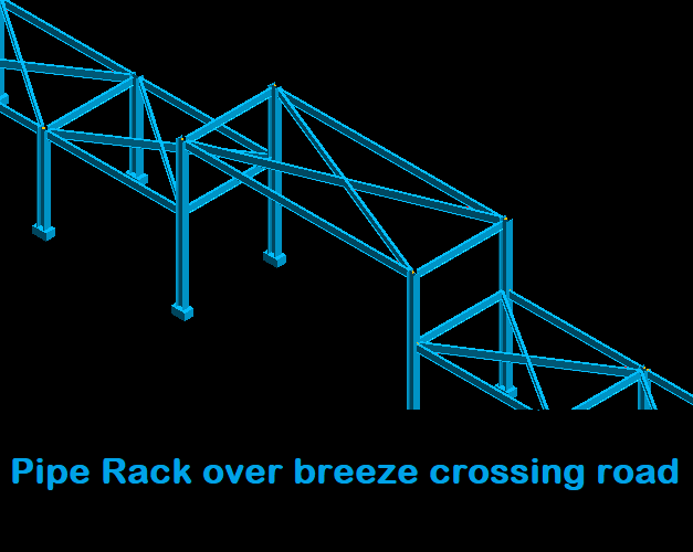
- If the pipe rack crosses the road, 4.5 m minimum height required for a general vehicle.
- 6 m for the truck.
- 7 m for the train.
- 8 m for a big crane.
Pipe Rack Lenght
The length of the pipe rack depends upon the number of units and the size of the plant. Rack length can be calculated using an overall plot plan. Rack bay length in most of the cases is 6 m.
You may also like
Hydrotest Procedure for Piping system
A Presentation on Pipe Insulation

Please send me the pipe rack calculation document pdf.my email is [email protected]
Okay
Sir, please send me also a sample calculation of pipe rack.
Thank you.
Hi sir, I am very interested in your material, can I ask for the calculation file for my study material?
[email protected]
Send me too at [email protected]
send me the same at [email protected]
Hi sir,
Please forward this calculation on my mail
[email protected]
SEND ME TOO PLEASE.
THANKS.
AT [email protected]
Hello, can you send me the same, please? at [email protected]
sir please send pipe rack calculation to my mail id [email protected].
How to select size of column,beam,spandrel ,size after calculating load and how to calculate ppe loads
Sir send me to at [email protected]
Please forward this calculation on my mail
[email protected]
Great and Powerfull Information.
Please Sir, May You Send To Me “The PipeRack Calculation Document” PDF ?
My e-Mail Is : [email protected]
Thanks a Lot.
Great information! Please send me a PDF document in [email protected]
Please send for me calculation of pipe rack.
Thanks
Please my email.
[email protected]
Clearly explained
Please send me pdf calculation of pipe rack
[email protected]
Please send me pdf calculation of pipe rack.
[email protected]
Please kindly assist me with the -The PipeRack Calculation Document-; my email: [email protected].
Thanks and Best regards
Musa
Es un gran trabajo, muy buen documento para estudiarlo. Es posible que me remita una copia del documento en pdf. mi correo es [email protected]
Desde ya muy agradecido.
Sure, Mr. Robert
Hi sir
I’m interested to calculate pipe rack support design,so please send me pdf file of pipe rack calculations
Hi,
I also want the pipe rack supporting document. Can you please send me on this mail I’d [email protected].
Did you get the file file
Hi Rehan,
It’s a great job! Do you can send me this document?
My mail is [email protected].
Thank you so much
Hi sir ,
im a graduate student that interested in your blog and wanted to learned more about piping and the structure to hold it.
Can you send to me calculation for piperacks?
My email
[email protected]
Send me pipe rack design calculation
Kindly send me pipe rack design calculatio please :
[email protected]
Thank you and with best Regards.
Hi Rehan,
Great work! I’m an intern in a aquaculture company that does a lot of pipe routing. I notice that most pipe racks are designed for plants. I think a fish farm would also benefit from pipe racks esp. when there’s limited space. Do you have any thoughts on this?
April
Hello April,
Yes, I agree, No facility can be limited to a single industry or application, with a modification in design per the project requirements, they can be used in fish-farming as well if the project budget permits.
please send me the design calculation of pipe rack.
could you please do me a favour !
please send me a design file (staad) of pipe rack.
kindly find my email id . [email protected]
Salve Rehan,
It’s a great job! Do you can send me the design calculation of pipe rack and some example?
My mail is [email protected].
Thank you so much.
Giuseppe
Great work sir
i just started my study in piping and layout . It will be very helpful if u could send the relevant document and other theory notes which will help me to develop my career.
email id : [email protected]
Can you please send me the design calculation of pipe rack?
My email address: [email protected]
Thank you very much!
Can you please send me the design calculation of pipe rack?
My email address: [email protected]
Thank you so much!
Can you please send me the design calculation of pipe rack PDF?
my email: [email protected]
Thank you so much.
Rehan Ahmad Khan,
you are a star, I don’t know how to thank you for the brilliant website. I am Mechanical Engineer work as a piping engineer for an oil and gas fields design company.
the information you shared are very useful, I wish to keep in contact with you in future.
Thank you sir and best regards,
Thank you Haithem,
I am glad you like it.
and High Five for sharing the same career 🙂
Sure! get connected on LinkedIn. I will be there always.
Can you please send me the design calculation of pipe rack PDF?
my email: [email protected]
Thank you
Awesome job.
Could you please send me a design calculation of pipe rack in PDF?
E-mail: [email protected].
Best regards.
Hi,
Great to see your study
kindly send connection drawings and design calculation in PDF
to [email protected]
Can u please send pipe rack calculation pdf copy to my mail id [email protected]
Thanks
I am glad you like it, thank you for the information
Hi Rehan Ahmad Khan,
I am a Structural Design engineer , I appreciate the knowledge your are share with us.
It will be very helpful if u could send the relevant document and other theory notes which will help me to develop my career.
email id : [email protected]
Dear Rehan Ahmad Khan,
Thank’s for your information, it’s very usefull since it’s relate to my job.Kindly send your calculation in pdf /xls sheet to me at [email protected]
Hi Mr.Rehan Ahmad Khan
Is it possible that if you have pipe rack msp file and 2 weekly also monthly report that you send me i need it for control project , thank you
Please send my email: [email protected]
🌹🌹🌹
please send me pipe rack design on [email protected]
great job..please send me the design and calculation pdf on
[email protected]
Hi Thanks for sharing information.
Can you please share this on mail and can you please share excel of pipe rack loading calculation on steel structure design ? My mail id is [email protected]
Please send me the file to [email protected]
[email protected]
I want to add one layer on existing pipe bridge. This to install two more 4 inch pipes.
How do I calculate if existing pipe bridge will support this!
Hi Rehan,
You are doing great job! Do you can send me this document?
My mail is [email protected].
Thank you so much
This content was good , pls share me pipe rack calculation pdf @ [email protected]
i am structural engineer with 25 years experience. Recently we got a job where i need to design structural for pipe rack and sleeper (max pipe size is 12″) for wastewater treatment. Can you kindly send me sample calculations. Please also recommend book or literature which is useful
thnx
Explained Well dear.
COnceptually its quiet clear to understand the calculation,
I am glad you liked it.
Hi Thanks for sharing information.
Can you please share this on mail and can you please share excel of pipe rack loading calculation on steel structure design ? My mail id is [email protected]
Great work sir
i just started my study in piping and layout . It will be very helpful if u could send the relevant document and other theory notes which will help me to develop my career.
email id : [email protected]
Please send me the pdf file to [email protected]
Please send me a copy of Pipe Rack Design and Calculation to my mail; [email protected]
Thank you so much.
sir glad to see ur blog
pls share me piperack design calculations PDF from civil structral point of view
my mail [email protected]
Dear sir,
Please send me pdf file. its interesting and knowledgeable.
[email protected]
Thanks.
Thanks for sharing
Thank you for your sharing.
I am glad that it helped to you.
Hi Thanks for sharing information.
Please send me the pipe rack calculation document pdf.
my email is [email protected]
ALWAYS CHECK PIPE LOAD STRUCTURE MEMBER SIZE WILL BE ACCORDINGLY
ALWAYS CHECK PIPE LOAD STRUCTURE MEMBER SIZE WILL BE ACCORDINGLY
Sir please send me idea about pressure drop calculation.
please send also me the report: [email protected]
HI SIR,
Kindly PLEASE send me pipe rack design calculation
[email protected]
THANKS
Hi sir, I am very interested in your material, can I ask for the calculation file for my study material?
[email protected]
Sir Rehan Ahmad Khan, I’m glad to see your blog,
Please share me, piperack design calculations in PDF from civil structure point of view,
my email [email protected]
Kind regards
Oswaldo Suarez
Looks very good and interesting. Can you also forward me a copy of the calcs?
Thank you very much. My email is [email protected]
H. Kelvin
AOA Sir!
Pl send me piping rack design calculation
Dear sir,
Please send me pdf file. its interesting and knowledgeable.
[email protected]
Thanks
Plz can anyone explain this point (Tier to tier distance can be calculated based on two elbows and one spool. It can also be considered as per the operating and maintenance requirement.)