Hydrotest, also known as the Hydrostatic test is a vital procedure in both construction and maintenance of the piping system. Before the new piping system runs into operation, it is necessary to make sure that, they are correctly commissioned, and are ready to use.
Also, proper maintenance of the piping system requires at some intervals (shutdowns). So, if any piping system susceptible to failure or leakage, it can be caught during preventive maintenance.
The processing industries may have many vessels and the piping network, that undergoes high-pressure. So it is required to perform a hydrotest to ensure ensures that the weld and flange joints are fitted properly by the fitters. It also ensures that used material is able to sustain the pressure, and the flowing fluid doesn’t leak out of the piping system.
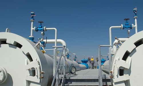
Table of Contents
Why to Perform Hydotest?
We must know the reasons behind the hydrotest performance. Let’s see some of the important points below-
Newly constructed piping systems are typically pressure tested. Older lines, that are already in service may be re-tested to ensure the piping system is still safe and reliable. Some times it is required to know if the same line is acceptable for the higher operating pressure or not for any modification in the system.
- To ensure the integrity of the piping system.
- To ensure the safety, reliability, and leak tightness of the pressurizes piping system.
- To check out the strength of weld joints and the materials used to carry the process.
- To inspect the flange joints.
- To ensure the smooth performance during the operational cycle
- To relieve the stresses from the system.
Types of Pressure Test
There are mainly two types of pressure test carried out in the industry-
- Hydro-static Test (Hydrotest)
- Pneumatic Test
Hydrotest
The hydrotest is performed by using water as the test medium.
Pneumatic Test
The pneumatic test is performed by using air, nitrogen, or any non-flammable gases.
In this article, we are going to talk about only hydrotest, So let’s understand the pressure-related terms below-
Pressure Related Terms
Pressure terms are as follows-
- Operating Pressure
- Design Pressure
- Maximum Allowable Working Pressure (MAWP)
- Hydro-test Pressure
Operating Pressure
An operating pressure is the amount of internal force applied to the inside walls of pipe and vessel during normal operating conditions. When a piping system is at its operating pressure, it generally runs at optimum performance.
Any failure to maintain operating pressure may cause the failure of the entire pressurized piping system.
Design Pressure
Design Pressure is the pressure at which the system is designed. In other words, You can say design pressure is the maximum pressure, that the piping system can be exposed to.
Maximum Allowable Working Pressure (MAWP)
MAWP is the maximum pressure that the weakest component of the piping system can handle. This is based on design codes and standards, back-calculation (from the fabrication of the piping system.
The MAWP should be clearly mentioned for vessels or pipes to figure out what pressures the system can withstand.
Note: The MAWP does not remain the same throughout the life of the piping system, and it may reduce due to corrosion, wear, and fatigue.
Hydro-test Pressure
The pressure at which the piping system is tested is always greater than the design pressure. If the system is hydro tested, it will never fail during operation.
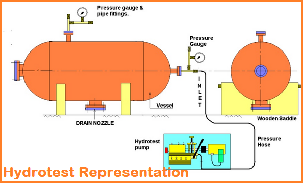
Apparatus used for Hydro-test
Following are the main apparatus used during hydrotest-
- Pump – To create pressure inside the system
- Hose and fittings – To connect the pump, piping system, and other equipment
- Test medium – Most of the time water is used as a test medium
- Pressure Gauge – To measure inside pressure
- Temperature Gauge – To notify the allowable temperature
- Torch Flash – For visual inspection of leakage
- Torque wrench – For proper tightening of joints
- Supports- To fix the pipe or vessel, before the test starts
The pressure gauges should be calibrated within a year, and the pressure range of gauge should not be less than 1.5 & greater than 4 times the hydrotest pressure.
Water Selection Criteria for Hydrotest
Using impure water from a lake or pond without any prior treatment for hydro testing has the possibility of damaging the piping system.
Although, the pipe is not going to corrode immediately, but the effect will be seen in the long run. If the contaminated water flows in the piping system for each hydrotest, then it can lead to corrosion, and further leakage.
So, we should prefer to use uncontaminated and treated water. Typically, it is not possible to get pure water at the construction site, fabrication yard, or at the operational unit. So, the water used in the hydrotest should be close to the drinking/potable water. Below are the general specification required for water-
- Percentage of Hydrogen (pH) – should be between 7 to 8.5
- Water Hardness – it should be between 150 – 400 ppm
- Calcium Hardness (Ca) – it should not be more than 80 ppm
- Magnesium Hardness (Mg) – below 40 ppm is acceptable
- Iron Content (Fe) – should be within 0.3 ppm
- Turbidity – allowed till 10 – 20 ppm
- Total Suspended Solids (TSS) – Should NIL
- Temperature – it should not be less than 17°C
In layman language, the water used for the hydrotest should be close to drinking or potable water. Generally, the companies have their own checklist to cross-check these parameters.
Water Volume Calculation
Let’s learn how to calculate the required water volume for testing-
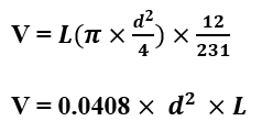
Where,
V = gallons required to fill at 0 psig
L = length of the test section (in feet)
d = diameter of pipe, inches (in inch)
You can put the input in the formula, and get the required water volume
Testing Pressure Table for Different Systems
| System | Code | Hydro-test Pressure | Pneumatic Test Pressure |
|---|---|---|---|
| Boiler Power | ASME Section I | 1.5*MAWP | Not Permitted |
| Power Piping | ASME B31.1 | 1.5*Design Pressure | 1.2*Design Pressure |
| Process Piping | ASME B31.3 | 1.5*Design Pressure | 1.1*Design Pressure |
| Building Services | ASME B31.9 | 1.5*Design Pressure | 1.25*Design Pressure |
| Sprinkler System | NFPA 13 | 200 psi | 40 psi |
NFPA: National Fire Protection Association
The above table is prepared as per the standard practices in the industry. The test pressure can also be calculated using the formula below-
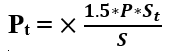
Where,
Pt = Minimum hydro-test pressure
P = Internal design pressure
St = Allowable stress at the test temperature
S = Allowable stress at design temperature
Note: the ratio of St/S should not exceed 6.5
(For getting the value of S & St, See Table A-1, Appendix A, ASME B31.3)
Preparation Prior to Hydrotest
- Prior to the hydrotest, the system should be flushed with a dedicated cleaning system to remove all dirt and foreign matter.
- Make sure the testing water is available as per the requirement
- Check all the welding is completed and approved by NDT Inspector.
- Make sure the pipe or vessel is clean from inside and are free from any slag or solid particle.
- Ensure the outer surface of the pipe or vessel is dry, for ease of visual inspection.
- Check the pressure gauge calibration report, also make sure the lower and upper limit is between 1.5 to 4 times the testing pressure to ignore the variation in the result.
- Make sure test temperature should not exceed 48° C
- Ensure the nozzle reinforcement pads are already tested at the workshop.
- All lines should be checked to make sure the piping system can be easily drained after testing.
- A high point vent should be kept open to displace the air from the pipe or vessel.
- Make sure all the joints are not insulated and are exposed to the inspector’s sight.
- Isolate all other equipment or pipes that are needed to exclude from the testing. It can be isolated using spectacle bling or blind flange.
- If the lines are having an expansion joint or spring support, use restraints temporarily to prevent excessive travel or deformation due to hydrotest load.
Testing Steps
Follow the following steps during delivery of hydro-test-
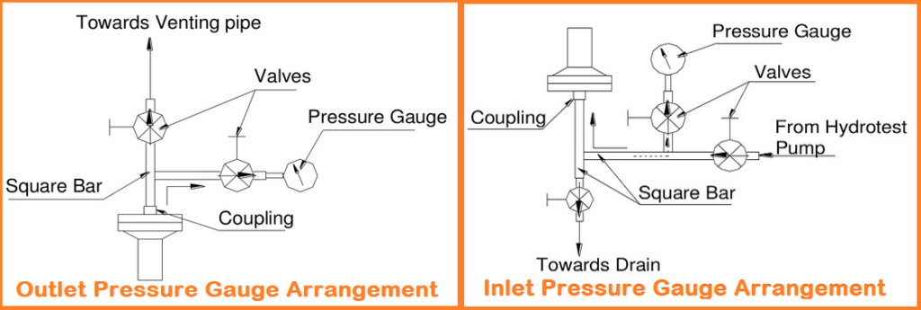
Step 1: Install the testing apparatus as explained above, refer figure: 2, if installation is done, Tight the nozzle, man-way, hand-way, and flange joint as per the required torque.
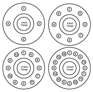
Step 2: Follow the proper tightening sequence to ensure the tightness of the flange joint.
Step 3: Start Filling the water in the pipe or vessel (after confirmation of vent opening and ppm requirement of water)
Step 4: Let the water over flow the high point vent or nozzle, so that the line become air free.
Step 5: Shut off the nozzle and allow the water flow from the top, and confirm the absence of the air bubble inside the specimen.
Step 6: If the line becomes air-free, then start the pump to pressurize the water inside the pipe of equipment. Pump selection is based upon the hydro-test pressure. Make sure the pump output pressure does not exceed the hydro-test pressure.
Step 7: Continuously take the reading from the pressure gauge to examine the current condition.
Step 8: Slowly increase the pressure as per approved procedure or as per previous experiences (During pressuring from design pressure to test pressure, make sure no one is standing near or on Piping joint).
Step 9: Now, hold the test pressure for a minimum of 30 minutes or as specified by the designer. Pay attention to the pressure gauge, as pressure should not get dropped during the holding period. At this stage, the pipe or vessel connections shall not be inspected closely, as it can be dangerous to the inspector.
Step 10: Reduce the pressure slowly to design pressure, now check for any leakage in the weld or flange joints. If no leakage is found, depressurizing can be started.
If there is any leakage in the system, depressurize the system, fix the problem, and again follow the steps 8,9 &10.
Step 11: Always depressurize the system slowly, never open the bottom nozzle initially, first open the high point vent, and then only open the low point drain to avoid any possible collapse due to vacuum created inside the pipe or vessel.
Note: Pressure gauge used for hydrotest once, can not be used again without calibration. If it is used, there will be variation in pressure reading.
Important Points to Consider During Hydrotest
- Orifice plates, spray nozzles, and similar flow restrictions instrument or component should be installed after completion of the hydro-test.
- If it is required to dismantle the piping system to perform testing, use less expensive gasket. After completion of the test, the test gasket shall be replaced with gasket specified in the PMS (Piping Material Specification).
- Fill the line slowly, this will enhance the probability of removing all air from the line.
- The testing pump should be connected at the lowest point of the line.
- Priming of the pump is required to remove all the air present in it.
- The pump should be isolated from the line to prevent back-flow.
Test Reports
After the completion of hydrotest, a report is generated that includes:
- Project number
- Job number
- Hydro-test duration
- Pressure gauge records
- Instrument’s calibration certificates
- Date-of-inspection/test
- Tag name or spool number
- Test medium
- Test pressure
- Test temperature
- Test results
- Remarks (if any thing to convey)
You may like
A Presentation on Pipe Stress Analysis
Olets Fittings: A Complete Guide
References
1. Pipeline Rules of Thumb – Fifth Edition ISBN 0-750674717
2. letsfab.in
3. weldinginspections.net
4. hanginghco.com
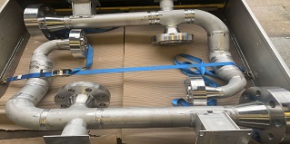
I would like to add the consideration if the piping spool are gone to be tested on the floor or in the shop before its final location in plant, be sure that it will supported properly before the test.
Thanks for pointing out the important point.
Thanks for the great information for us.
Found your post interesting to read. I can not wait to see your article
shortly. Good Luck for the upcoming update.This article is really quite interesting and effective.
Best regards,
Dinesen Raahauge
Glad to hear that Mr. Dinesen
Very valuable information, it’s not at all blogs that we find
this, congratulations I was searching for something like this and found it here.
King regards,
Thompson Raahauge
Thanks, Mr. Thompson
In ASME B31.3 the maximum allowable stress at test condition was not clearly defined ( ” As said in ASME SECTION – I – PG99.1 No part of the boiler shall be subjected to a general membrane stress greater than 90% of its yield strength “).
There is one para in ASME B31.3 para 345.2.1 Limitations on pressure, can we take, that at any point of time the stress generated during hydro test should not exceed the yield strength of the part ?
theoretically the hydrotest “Test pressure” will never reach the yield strength of material. take one step back during WT of pipe calculation. during WT calculation, take as sample material A105 based on Table A-1M, Ts: 483 MPa, Ys: 248 MPa, SA at room temperature is 161 MPa, in the case of A105 case the SA is calculated based on Ts instead of Ys.
The calculation of SA is 2/3 of Ys or 1/3 of Ts which one is lesser – this option basically to ensure the lower SA is selected during WT calculation
During hydrotest the stress increase 1.5 times, in case of A105 the stress approx may reach 1.5 x 161 = 241 MPa. this value is lesser than 248 MPa
and one shall be noted as well that during WT pipe calculation additional WT such as fabrication tolerance 12.5% and CA (normally 3 -3.2mm) the impact is higher “resistance” to stess
My pump pressure reading is 130 kg/cm2 and my hydro test pressure reading is 160 kg/cm2.
Is there any issue with the gauge?
Whether my pump pressure reading and hydro test pressure reading should be the same initially during the test?
No, pressure at both locations may vary, the pump produces constant pressure, but when the fluid gets compressed and compressed inside the vessel at constant pressure, the pressure inside the vessel shall be increased. This could be the case for your pressure difference reading.
thanks to great and good information for me
Thanks, Madhu
Dear
Rehan Khan
You not include Hydrotest inside PSV and NRV important Equipment in Hydrotest
Hi Ahmad
Please explain the pressure gauge section as per ASME Sec Viii UG-99 Test Pressure min 1.5 times to Max 4 times, but we have selected Max 4 time’s will the accuracy level digress. Any solution
It’s a detail one for me. Thanks for the info.
Thank you for your valuable procedure regarding hydro test .But here not mentioned the safe distance during hydro ,pneumatic tests. Please confirm