This article will introduce you to the control station, control valve, design consideration for control station and control valve, different arrangements of control station assembly, and layouts.
Table of Contents
What is the Control station?
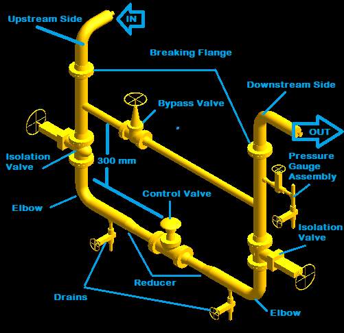
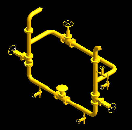
Control Station is an arrangement of piping and piping components in which the control valve is used to reduce or to regulate the flow or pressure of the piping system.
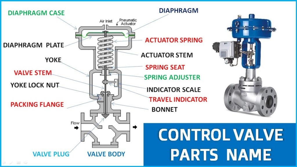
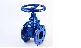
What is the Control valve?
A control valve is a valve, used to control fluid flow by varying the size of the flow passage as informed by a signal from a control room. This allows the direct control of flow rate and the consequential control of process quantities such a pressure, temperature, and liquid level in the process piping system. You can see the Principles of Operation of the control valve.
Note: Any Regulation Valve can be converted into Control Valve
- Globe Valve
- Needle Valve
- Butterfly Valve
- Diaphragm Valve
- Piston Valve
- Ball Valve
- Plug Valve
- Pinch Valve
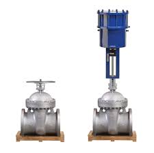
- All the above valves can be converted into a control valve by adding actuator to them (regulation Valve with actuator is control valve)
Important Points for Control Valve
- Control Valve comes under the scope of the Instrumentation Department.
- Information about the control valve can be found in Hook Up Drawing.
- Sizing of the control valve is done by an Instrument Engineer.
- Control valve size is one or two sizes smaller than line size in most cases.
- Rating: Higher than the line rating.
What do you mean by Actuator?
An actuator is a component of a machine or equipment that is responsible for moving and controlling a mechanism or system.
An actuator requires a control signal and a source of energy for converting the source’s energy into mechanical motion. For example, you can see the control valve, the actuator mounted on the valve helps to opening and closing of the valve automatically. The control signal is relatively low energy in the form of voltage or current. The source of energy could be in the form of pneumatic, hydraulic, electric energy, or even human power.
Types of Actuator
- Pneumatic Actuator- Powered by compressed air
- Hydraulic Actuator- Different liquids are used as a source of energy
- Electric Actuator- Electric energy is used to drive such actuators
Design Consideration for Control Station
- The control valve should be flange end for ease of removal during maintenance.
- The control valve and it’s connecting flange, gasket, and fasteners should be of a higher rating than the line rating.
- The size of the control valve will be one or two sizes smaller than the line size.
- Reducers are required at both sides of the control valve to joint different diameters of the pipe, because of the different sizes of the line and control valve.
- Concentric reducers can be used to maintain the flow pattern, but for ease of support eccentric reducer flat side down is preferred.
- Drains are required at both sides of the control valve to equalize pressure between the isolation valve and the control valve.
- The upstream drain is used, if the control valve fails to open and both the drains are used, if the control valve fails to close.
- Drains can be welded directly on the reducer if the reducer size is more than 8″.
- Isolation valves are required at both sides of the control valve for isolating the line during the maintenance work.
- The size and rating of the isolation valve should be the same as the piping flange rating and the size.
- The bypass is required to keep the system in running condition during control valve maintenance.
- Bypass size should be the minimum same as the control valve’s size.
- Globe valve should be preferred as a bypass valve as it is the best regulation valve.
- The bypass valve should be located upstream side to avoid fluid hammer on the bypass valve disc.
- A pressure Gauge is required in the control system to measure and control the pressure during maintenance.
- The pressure Gauge should be located downstream side of the control valve after the bypass.
- Control Station is kept at the operating level for ease of maintenance, which should be a minimum of 500 mm to 600 mm above the operating level.
- Supports are required at both sides of the control valve to take care of the weight.
- support should be a minimum of 300 mm away from the flange joint for removal of the bolt.
- Support can be allocated either below the reducer or elbow.
- To take care of the thermal expansion and to make the system stress-free both supports should be resting support.
- In case of vibration downstream side support should be anchor support and the upstream side should be resting support.
- Axial and guide support can be used for controlling the pipe movement.
Different Arrangement of Control Station
If the control valve is up-to 25 kg then there is no need for lifting arrangement however, it is a decision of the client. It can vary company to company
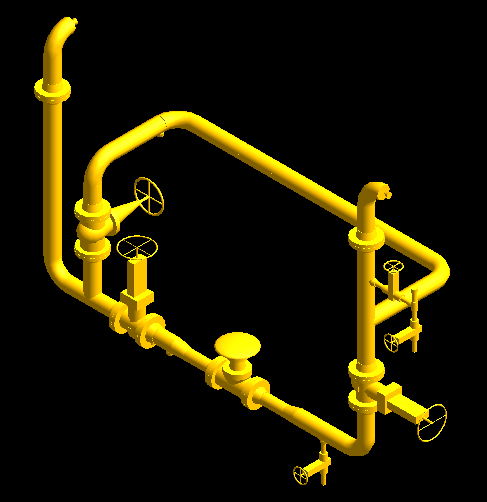
Arrangement 1
If there is no lifting arrangement required for the control valve then bypass can be kept 300 mm above the control valve. Refer to Fig. 1.
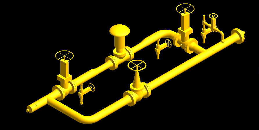
Arrangement 2
In case of lifting arrangement bypass should be opposite side of operating area till 1.7 m height for ease of operating . Refer to Fig. 4.
Arrangement 3
If bypass valve is crossing the height above 1.7 m because of larger line size then shift upstream side isolation valve in horizontal line and put bypass before that isolation valve. Refer Fig. 5.
Arrangement 4
Control valve above 12″ normally are preferred sandwich type arrangement, where bypass is at same level for ease of supports. Refer Fig. 6.
You may also like
Olets Fittings: A Complete Guide
A Presentation on Pipe Insulation
A Presentation on Pipe Stress Analysis
Control Station and Control Valve in the Process Piping

In your article for control valve station you stated ” Bypass valve shall be installed towards upstream to avoid hammering”. Can you please provide reference where you have read it?
Very good demonstration of control valve assembly.
Thanks for your read