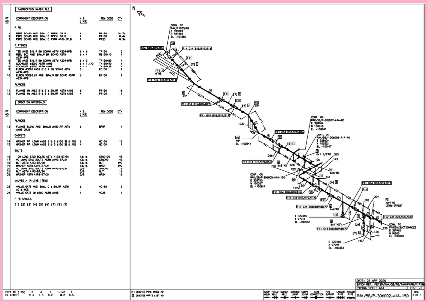
Piping isometric drawing is a very essential document, as it is used for construction at the site or the workshop. The piping isometric drawing should be thoroughly checked. The drawing should not be issued for construction without checking and approval. Any error in the drawing can lead to the cost and delay to the project. Only IFC (Issued for Construction) isometric drawings are used by the fabricator to execute error-free work. Every organization uses its own checklist for isometrics drawing, the checklist can vary from company to company. This article includes a typical checklist for piping isometric drawing.
Documents Required for Checking Piping Isometric Drawing
| Documents | Uses |
|---|---|
| P&ID (Piping and Instrumentation Diagram) | To cross-check line number, line size, insulation, special requirement notes (like no pocket, press head), etc. |
| Line List | To check Design Pressure & Temperature, stress critical lines, Hydro test pressure, inspection class and type, etc. |
| GAD (General Arrangement Drawing) | To check line route, dimension, elevation, valve orientation and co-ordinates |
| PMS (Piping Material Specification) | To check materials detail |
| Equipment Drawing | To check line connections |
| Nozzle Orientation | To check elevation and orientation of connected nozzle |
| Piping Support Drawing | To check support’s allocation |
| Special Items Detail | To check special items type and their dimensions |
| Instrument Hook-up | To check the connection/end requirements for mounting the instruments. |
Checklist: Piping Isometric Drawing
The isometric drawing sheet consists of four major parts viz title block, drawing area, BOQ (Bill of Quantity ) section, and Special requirement notes section. Here, you will learn to check the piping isometric drawing section-wise for ease of learning. It helps to deliver error-free work.
Title Block
Make sure that, the below mentioned points are specified in tittle block
- Line Number
- Isometric Drawing Number
- Sheet Number
- P & ID Number
- Piping Layout/GAD Drawing Number
- Project Name, Project Code and Area Code
- Insulation and Heat Tracing Type (If the line is insulated only)
- Line Testing Type.
- Inspection Class
- Hydro-test / Pneumatic test pressure
- Design Pressure and Design Temperature (It’s not mandatory)
Drawing Area
Points to be checked at drawing area are as follows-
- Iso North
- Equipment name and location
- Co-ordinates for all equipment
- Nozzle orientation
- Nozzle size and tag
- Angle allocation and direction (clockwise or anti-clockwise)
- Nozzle centreline elevation
- Line elevations (it can be centerline or BOP (Bottom of Pipe) elevation)
- Line offset angle and direction
- Slope (if it’s required as per project)
- Line number with complete spec detail
- Spec break (If required)
- Dimensions of all components and spools
- Fluid flow direction
- Support locations
- Continuation isometric drawing number (if the complete line do not fit in the single sheet)
- Instrument location and tagging.
- Valve orientation
- Control Valve location and arrangement.
- Grid location
- Special Items Tagging
- Orifice Meter straight run requirement
- High point vents and low point drains
- Drains and vents for hydro testing
- Structural penetration (if the line is crossing any structure)
- Pressure and Temperature gauges
- Field weld and Workshop weld Identification
- Reducer size
- Branch size
- Minimum gap requirement between the welds
- Spool sequence number
- Orifice meter taps orientation (it depends upon the pipe direction and fluid type
BOM [Bill of Materials] Section
BOM section is a very important section, as it affects the cost of the project. Check the below points wisely-
- Component Description
- Component Quantity
- Commodity Code
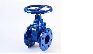
- Valve type and quantity
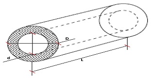
- Piping component size and rating
- Codes and Standards (Pipe Schedule Number)
- Non-piping component BOM should not include on isometric drawing
- Do not include the “on hold” materials
- Special items, instruments, and pressure assembly should be tagged
- Spool length and size
- Types of pipe support and their quantity
Special Requirement Notes
This section totally depends upon the project nature and their specialty. If anything required to communicate. The process/design engineer mention the note text in this section. I’m mentioning some of the examples below-
- Check if any slope requirement mentioned in P&ID
- No pocket ( We should ignore pocketing in the suction line, if the fluid flowing is corrosive in nature or in the food processing industry)
- Minimum or Maximum distance, straight length requirements, pressure head requirement, etc. (as per P&ID).
- Breakup flange requirement for spool removal for ease of maintenance
This checklist is not limited to these points only, it can vary project to project or line to line. These are the basics and mandatory points to be checked.
You may also like
Olets Fittings: A Complete Guide
A Presentation on Pipe Insulation
A Presentation on Pipe Stress Analysis
Control Station and Control Valve in the Process Piping

Amazing Content Rehan! All the best for this wonderful initiative
Thanks Vrishal
Good work and include NDE details, painting specs, insulation will enable to guide the working team.
PWHT also. (Post Weld Heat Treatment) if any
PWHT also. (Post Weld Heat Treatment) if any. +234-817-2425-219
Pipe support not included on the BOM?
Although, that pipe or vent pipe we need pipe support to hold the pipe line.
Hello Felipe,
Yes, BOM section also includes the type of pipe support and their quantity. I have updated in the post.
Like!! Really appreciate you sharing this blog post.Really thank you! Keep writing.
Glad you liked it
An attention-grabbing discussion is worth comment. I believe which you need to write a lot more on this matter, it won’t be a taboo subject nonetheless typically persons are not sufficient to speak on such topics. Towards the next. Cheers
Thanks for reading and a valuable feedback.
Cheers!
Consider to add:
1. CHECK THAT THE PIPE ROUTING AND ALL SUPPORT DESIGN IN THE ISOMETRIC DRAWING MATCHES THE LATEST PIPE STRESS ISOMETRIC MARKED-UP FROM STRESS TEAM.
2. CHECK THAT ALL NOTES IN STRESS REPORT WAS INPUT CORRECTLY IN ISOMETRIC DRAWING.
3. CHECK THAT BOLT LENGTH IS SUITABLE FOR INSTALLATION AND REMOVAL
4. CHECK THAT ALL SPECIAL REQUIREMENT FOR DISSIMILAR MATERIAL CONNECTION WERE CONSIDERED:
+ WELD OVERLAID (MATERIAL + DESCRIPTION)
+ INSULATING KITS
Thanks! Tung,
Yes, these points can be added to the checklist.
Great delivery. Sound arguments. Keep up the great effort.
This site was… how do you say it? Relevant!! Finally I’ve found something which helped me. Many thanks!
I truly love your blog.. Great colors & theme. Did you make this website
yourself? Please reply back as I’m attempting to create my own blog and would like to find out
where you got this from or just what the theme is called.
Many thanks!
I could not resist commenting. Perfectly written!
Informative article, exactly what I wanted to find.
Wow, fantastic weblog layout! How lengthy have
you ever been blogging for? you make running a blog look easy.
The entire glance of your web site is wonderful, as neatly as the content material!
Thanks for sharing!
In documents you can add ‘Instrument hook-up’ as well.
It will use to know Connection/End require for mounting the instruments.
Thank you! Parth
I have updated your valuable point. Cheers!
Finally I’ve found something which helped me. Many thanks!
KEEP ON GOING.
Thank You!
Thank you sir. Wonderful piece
1.Iso lines must be located proximity to an equipment of known location.
2. Consider to cut isos flange end to flange end unless the line is too long
3. Elevation and distance of pipe deck penetration if any