Pipe wall thickness calculation is a very important activity in the career of a piping engineer. You may need to calculate numerous pipe wall thicknesses for different design conditions.
The process plant piping system deals with the fluids that flow inside the pipe at high pressure and temperature. The high pressure inside the pipe leads to high circumferential pressure on the pipe wall.
Whereas the high temperature causes thermal expansion in the pipe, which exerts tremendous pressure on the pipe wall, at the same time, the high temperature reduces the stress-withstanding capacity of the pipe.
Hence, the effect of pressure and temperature can lead to bursting or damage to the pipe if the pipe wall thickness is not enough to withstand it.
The piping designers need to find out the required pipe thickness as per paragraphs “304.1.1 & 304.1.2 (straight pipe under internal pressure) of ASME B31.3” to bear the inside pressure of the pipe or line.
In this article, we will learn the steps with an example for pipe thickness calculation as per ASME B31.3. Before proceeding with the calculation, we shall require the inputs.
Table of Contents
Inputs Required for Pipe Thickness Calculation
Following are the required inputs for pipe wall thickness calculation. We shall use the same inputs for our thickness calculation:
- NPS (Nominal Pipe Size or Line Size): 6”
- MOC (Material of Construction) of the pipe: ASTM A106 Gr. B
- Manufacturing method of the pipe (SMLS, EFW or ERW): SMLS
- Design Pressure: 20 Mpa
- Design Temperature: 100° C
- Mill Tolerance of the pipe: ±12.5%
- Corrosion Allowance: 3 mm
- Erosion Allowance, if applicable: 0 mm
- Mechanical Allowance, if applicable: 0 mm
Note: If there is any chance for the erosion due to the fluid nature or the flow pattern then it need to be considered as erosion allowance. Also, if any thread or groove to be made on the pipe then the groove and thread depth to be considered as mechanical allowance.
Abbreviations
SMLS: Seamless
EFW: Electric Fusion Weld
ERW: Electric Resistance Weld
Now that we have the required inputs, let’s understand the formula for pipe thickness calculation
Pipe Wall Thickness Calculation Formula
We know from ASME B31.3, Paragraph 304.1.1, Equation (2):

We also know from Paragraph 304.1.2, Equation (3a)

Where,
tm = minimum required thickness, mm
t = pressure design thickness, mm
c = sum of corrosion + erosion + mechanical allowances, mm
P = internal design pressure, Mpa
D = outside diameter of pipe as per ASME B36.10M or ASME B36.19M, mm
S = allowable stress value for pipe material as per Table A-1M of Appendix A, Mpa
E = basic quality factor for longitudinal weld joints in the pipe as per Table A-1B
W = weld joint strength reduction factor in accordance with para. 302.3.5(e) & Table 302.3.5
Y = coefficient from Table 304.1.1
Note: The above equation (3a) is applicable for t < D/6 (thin wall).
For t ≥ D/6 (thick wall) or for P/SE > 0.385, the calculation of internal design pressure thickness for straight pipe requires special consideration of factors such as the theory of failure, effects of fatigue, and thermal stress. This condition rarely comes into application.
However, to cross-check the above condition, first you need to calculate the pressure design thickness (t) using equation (3a). Therefore, you do not need to be bothered about the said condition; go for the calculation directly.
I hope the formula is clear to you. If not, for sure, you will understand it after going through the example calculation.
Pipe Thickness Calculation Example
Let’s calculate the wall thickness for 6″ seamless pipe having material ASTM A106 Gr. B, design pressure 20 Mpa, design temperature 100 °C, corrosion allowance 3 mm, erosion allowance 0 mm, and mechanical allowance 0 mm.
From the above inputs we have,
c = 3+0+0 = 3mm
P = 20 Mpa
Now we need to get the value for D, S, E, W, & Y.
Let’s get it one by one.
D: Outside Diameter of the pipe
The equation for the pipe wall thickness is based upon the outside diameter of the pipe because the outside diameter of the pipe is constant. Whereas the inside diameter of the pipe varies as per the pipe wall thickness.
We can get the outside diameter of pipe from the below standards:
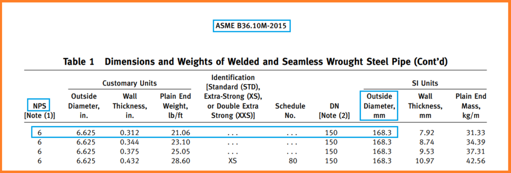
- ASME B36.10M: for wrought steel pipes
- ASME B36.19M: for stainless steel pipes
Note: Both standards will have the same value, so we can refer to any of them.
Referring to the below image from ASME B36.10M, we can see that the outside diameter (D) for 6″ pipe is 168.3 mm.
S: Allowable Stress value of the Pipe Material (ASTM A 106-Gr. B) at Design Temperature (100°C)
For getting the allowable stress value (S), we need to refer the Table A-1M of ASME B31.3.

From the above table, we can see that allowable stress (S) for pipe material A106 Gr. B at design temperature (100°C) is 138 Mpa.
Note: The allowable stress may be interpolated for intermediate temperatures.
E: Basic Quality factor for longitudinal weld joints in the pipe
The value of E (Longitudinal Weld Joint Quality Factor) can be found in Table A-1B of the ASME B31.3. The weld joint factor (E) is 1.00 for our case as the pipe material is A106 and the manufacturing method of the pipe is seamless. Refer below table for your reference.
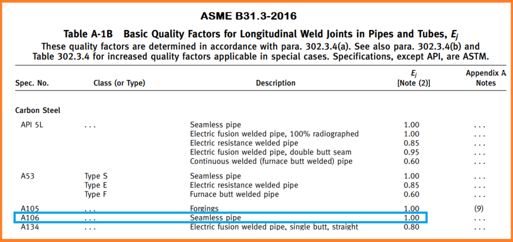
Note: The Longitudinal Weld Joint Quality Factor (E) for seamless pipe is always 1.00 as there is no longitudinal weld present in the pipe. And for welded pipe this value shall vary as per the welding method used during manufacturing and the radiography done on the pipe to check the weld quality.
W: Weld Joint Strength Reduction Factor
At elevated temperatures, the long-term strength of weld joints may be lower than the long-term strength of the base material. This is why the weld joint strength reduction factor (W) is mandatorily needed to be considered for welded pipe thickness calculation.
As per para. 302.3.5 of ASME B31.3, The weld joint strength reduction factor (W) is the ratio of the nominal stress to cause the failure of a weld joint to that of the corresponding base material for an increased or elevated temperature condition of the same duration. It only applies at weld joints in longitudinal or spiral welded pipes.
The value of W (weld joint reduction factor) can be found in Table 302.3.5 of ASME B31.3 for welded pipe. And for seamless pipe, it can be considered as 1 by default. For our case, the value of W is 1. Refer below table for your reference.

Y: Values of Coefficient for t<D/6
The factor “Y” depends upon the temperature. At elevated temperatures, the Y (value of coefficient) increases, and it leads to a decrease in the calculated required pipe wall thickness. Y is used to address the increased ductility of piping materials as the temperature increases.
Refer Table 304.1.1 of ASME B31.3 for getting the value of Y.
For our case, pipe material is A106 Gr. B and the design temperature is 100°C. Therefore, Y shall be 0.4. Refer below table for your reference.
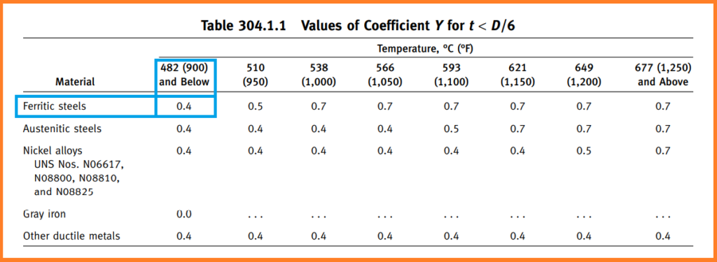
The value of Y may be interpolated for intermediate temperatures.
Now, we have all the required values as below:
P= 20 Mpa
D = 168.3 mm
S = 138 Mpa
E = 1
W = 1
Y =0.4
Let’s put these values in equation (3a).


Now, we need to refer ASME B36.10M to check the nearest higher thickness available as per the standard.

From the above table, we can see the nearest greater thickness available is SCH160, 18.26 mm.
Note: For seamless pipe, we move Schedule to Schedule or Identification to Identification; we do not select the thickness other than inline with Schedule Number or Identification.
As per para. 304.1.1(a) of ASME B31.3, the minimum thickness, T, for the selected pipe, considering the manufacturer’s minus mill tolerance, shall be not less than tm.
Therefore, for getting the T, we need to subtract the mill tolerance from the selected pipe thickness
We know that from the inputs, mill tolerance is given as ±12.5%
So,
Mill tolerance = (Selected pipe thickness / 100) 12.5 = (18.26/100) 12.5 = 2.28 mm
Therefore,
T = Selected pipe thickness – Mill Tolerance = 18.26 – 2.28 = 15.98 mm
Now, we have T = 15.98 mm & tm = 14.53 mm
We can clearly see that T is not less than tm
Therefore, the selected pipe thickness, SCH 160, 18.26 mm, is accepted.
Note: If the condition “T > tm” would have not met then we will have to select the next greater thickness from the standard until the condition meet.
We can also see that t < D/6. Therefore no special consideration of factors such as theory of failure, effects of fatigue, and thermal stress is required.
I hope You have got the overview of the pipe wall thickness calculation, You can practice for other cases following the mentioned steps for better understanding.
Few Important Posts
Pipe Rack Design and Calculations
Pipe Wall Thickness Calculation For External Pressure or Vacuum
Hydrotest Procedure for Piping system
Olets Fittings: A Complete Guide
Reference
ASME B31.3

Send me hard copy.
Hi,
could you give me a example based on 302.2.4 of ASME B31.3 (for temporary condition wall thickness calculation)?
Table 326.1 (e.g., ASME B16.9, B16.11, and B16.28) state that pressure-temperature ratings are based on straight seamless pipe. Except as limited in the standard or elsewhere in this Code, such a component, made of a material having the same allowable stress as the pipe shall be rated using not more than 87.5% of the nominal
thickness of seamless pipe corresponding to the schedule, weight, or pressure class of the fitting, less all allowances applied to the pipe
Keep this going please, great job!
Thanks for this blog. Helped me a lot to calculate pipe thickness for Pharma Project. Can you share Allowable Stress Value of Pipe Material table for Stainless steel SS316L?
Keep doing good Job. i love to read your posts
Thanks, Sandeep
Please refer the Table A-1 of ASME B31.3 to get the allowable stress value.
Thank You Rehan. Found it.
Dear Rehan
Greetings
can you please share excel sheet for Internal.and External Pressure Calculations
24″ – Astm A 333 Gr 6 , 31mm ,Operating Pressure-65 bar , Temperature 34°C
24″ – API 5L X 65 , 11.9 mm ,Operating Pressure-65 bar , Temperature 34°C
Hi Rehan,
Do you know equivalent European Standard to ASME B31.3?
Hello Sandeep,
It is EN13480
thank you Rehan,
frp piep wate calculation ples sar
frp piep wate calculation ples sar
Please Check t …D=14″/P=503psi/A106GrB/at 400C deg
(503×355.6)÷(2×13800+2×0.4×503)~6.39 mm Without any allowance
Hello, thanks for clear explanation!
Just one question appaired. How to determine exact formula of min wall thickness for pipe pressure class?
There are 2 formulas, the first one (3a) you have used is for temperature Class up to 2500.
From which pressure works 2nd formula (3b) for classes above 2500?
Hello, Thank you very much for your very useful and practical article on calculating the thickness of pipe under internal pressure.
Please prepare an article in the same way for Straight Nonmetallic Pipe Under Internal Pressure. pipes such as Thermoplastic pipes, RTR {Laminated) Pipe and RTR {Filament Wound) and RPM (Centrifugally Cast) Pipes.
Sure, I will write soon on non-metallic pipe thickness calculation.
Thank you!
tm = tc + 12.50 % (mill tolerance for seamless pipe is 12.5 %)
12.5 % of 9.38mm length we have to find?
=tc/0.875 (how we get this eqn?)
= 9.38/0.875
For pressure vessel the nozzle sch is not given but only rating like 300# 0r 600# how do we find the schudle
Can you share Allowable Stress Value of Pipe Material table for FRP PIPES?
it is not constant