Miter Bend or Miter Elbow plays an important role in the piping or pipeline engineering field. Because standard Fittings (Elbows) are not easily available and economical for the large pipe sizes. The field engineer or the fabrication supervisor is responsible for the perfect delivery of the joints made for the installation of the miter bend.
In this article, We will learn detailed calculation procedures for finding out the required dimensions, miter offset, angles of cut, and weight of the pipe required for miter bend.
Table of Contents
Fittings Used for Direction Change
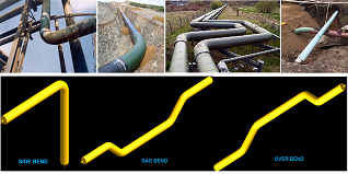
There are mainly three types of fittings used for changing the line direction-
- Standard Elbow – Forged or casting fitting |used in high-pressure lines
- Pipe Bend – Cold pulled bend| mainly used in the transportation pipeline or if the pigging is required in the pipeline.
- Miter Bend – Fabricated Fittings | Can be fabricated at site or workshop | mostly used in general services
We will not dig deeper for the other fittings, but an overview was required. So, let’s move to the miter bend.
Introduction to Miter Bend
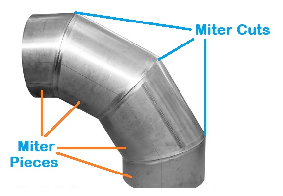
A Miter Elbow is a fabricated fitting used for direction change of the line. It is prepared by mitering (a cut at an angle) and then welding the pipe ends of the cut pieces to form a required bend, usually at 45° and 90°.
Miter Elbow or Bend is made from miter cut pieces of pipe and the number of cuts and miter pieces is decided based upon the pressure and temperature the particular line carries. The miter pieces also known as gores or pipe-segments. There are two end segment and two middle segment in a 4-piece Miter bend.
Codes and Standards Related to Miter Bend
ASME 31.3, Section 4
Pressure design of miter bend
AWWS C208-96 (American Water Work Association)
For sizing, dimension specifications, application, design consideration, and the number of cuts or miters.
ASME B16.9
For bevel or butt weld end preparation of the miter pieces
ASME B16.5
For flange end miter bend
Important Note: according to ASME B 31.3, the number of miters in the “miter bend” is restricted to a maximum of 5, as more the weld joints lesser the strength
Key Points for Miter Bend
- Miter bends are fabricated fittings
- It is also called Miter Elbow
- The thickness of the pipe used for the miter bend may differ from the line to be connected.
- Highly skilled manpower is required for perfect mitering, end preparation, and welding performance for miter elbow
- Miter-bends are mainly used in general services (category “D” fluid)
- If used at onsite (process lines) then 14″ NPS and above (not fixed)
- Used above 6” for offsite (utility lines) application.
- Miter bend can be fabricated with 2, 3, 4, & 5 miters or cuts as per the design conditions.
- The radius of miter bends can be R=1D, 1.5D 2D, 3D, 5D, 6D, 8D, 10D, or Customized per the requirement.
Note:
1. Category “D” fluid means non-hazardous fluid like water.
2. The number of miters is decided based upon the pressure and temperature of the line.
3. Miter bend application size range may vary from project to project and company to company.
Limitations of Using Miter Bend
- Poor strength due to more number of weld joints
- Pressure drop is higher due to friction and restrictions of the flowing fluid
- Higher turbulence
- Higher risk of corrosion because of more weld joints.
- Not economical for lower line sizes
- High skilled welders and fitters required
- It is not suitable for pigging
- Miter elbows are restricted to low-pressure lines only
- Stagnation of fluid, which can cause corrosion and contamination of flowing fluid
Advantages of Miter Bend
- Low-cost compare to standard elbow
- No thinning required, whereas thinning is required for cold pulled bend
- It can be fabricated at the site or at the workshop
Inputs Required for Miter Bend Calculation
Line Size: 10″ NPS
Line MOC: Carbon Steel (A106 Gr. B)
Schedule Number: SCH 120 (for selecting the pipe for cutting the miter pieces or for calculating the pipe weight)
Bend Angle: 90°
Number of miters or cuts: 4
Radius of Miter Bend: 3D = 3*10*25.4 = 762 mm
Calculation Steps
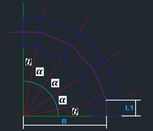
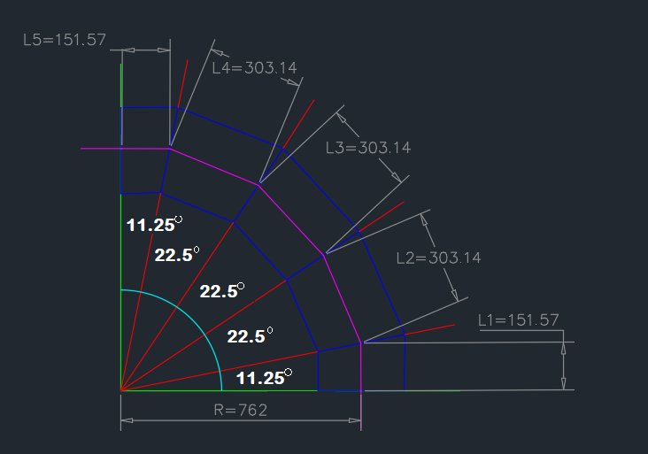
Step 1: As per the number of cuts, draw the sketch as below (refer to Fig 2)
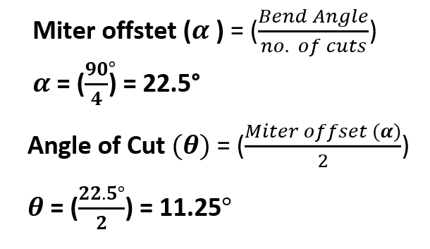
Step 2: Calculate miter offset and angle of cut![]()
Step 3: Now calculate the Length L1 with the help of the angle of cut
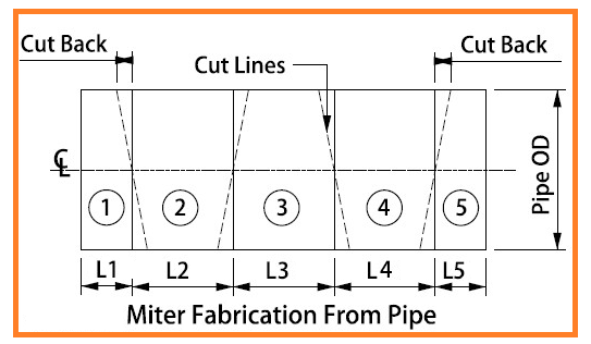
Refer to the below figure for understanding the lengths L1, L2, L3, L4, L5, and the cut-back, these dimensions are required to calculate to fabricate the miter elbow or bend.
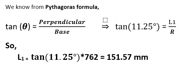
Now, Referring fig 2, apply the Pythagoras formula to get the length L1
Thumb Rules
1: The first and the last miter pieces will be of the same length for any cases
2: Other than the last miter piece, all the miter pieces will be the double of the first miter length
Therefore,
For our case, L1 = L5
So,
L5 = 151.57 mm
Similarly,
L2 = 2*L1 = 2*151.57 = 303.14 mm
also,
L3 = 303.14 mm
L4 = 303.14 mm
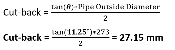
Step 4: Calculate the Cut-back (refer figure 3)
Formula for Cut-back is as below
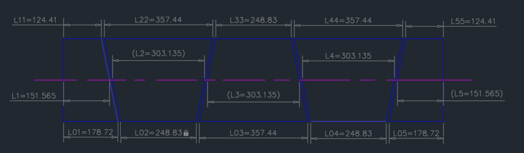
Note: We can also calculate both sides length of the miter pieces using the Pythagoras formula. We just need to add the pipe radius to R for outer length and subtract the pipe radius to R for inner length. You can cross-check with the calculated length (refer below figure).
Step 5: Calculate the “total length of the pipe required” for the miter elbow or bend.
The total length of the pipe required = L1+cutting allowance+L2+cutting allowance+L3+cutting allowance+L4+cutting allowance
Note:
1. Cutting allowance depends upon the method used for cutting the miter pieces. Let’s assuming cutting allowance 5 mm
2. For calculating total length, you can take any length (side or center), the result will be the same (refer fig 5).
We are calculating here with the center lengths
Thus,
L = 151.57+5+303.14+5+303.14+5+303.14+5+151.57
L = 1232.56 = 1233 mm
Step 6: Find out the weight of the pipe required for miter elbow
Check the Plain End Mass of the 10″ NPS pipe of SCH 120 in the “ASME B 36.10 (for our case refer below figure)
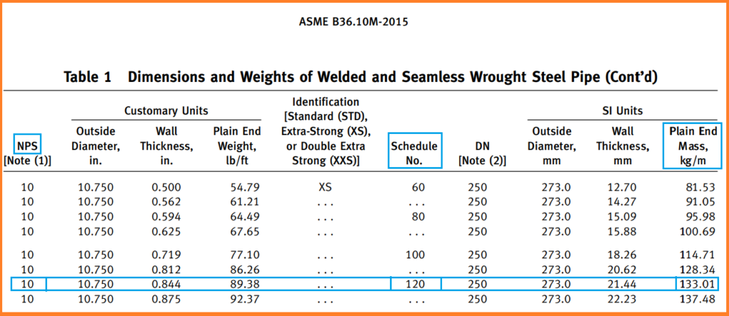
Plain end mass for 10″ SCH 120 in ASME B36.10M is given 133.01 kg/m
You can also find out the Schedule number of any pipe
Now,
find the weight of the pipe using the following formula-
Weight of the Pipe = Plain End Mass * Length of Pipe ( always in meter)
Weight (W) = 133.01 * 1.233 = 164 kg.
These were the all major topics related to miter bend fabrication.
You may also like
Pipe Rack Design and Calculations
Hydrotest Procedure for Piping system
PDMS Commands: Piping, Equip, Structure & Draft
Olets Fittings: A Complete Guide
A Presentation on Pipe Stress Analysis
1000 miter data
Make a post regarding,
Pipe Bend calculation( Tangent length,Arc Length,Matching diagonal)
How to see a isometric Diagram and what are the meaning of symbols and alphabets that are mentioned in the drawing
how calculation for hoop stress for miter bend acc. AWWA M11