Pipe wall thickness calculation for piping systems under external pressure or vacuum condition, Jacketed Piping, underwater pipelines, etc. required to consider stress inside the pipe, compression capability of the pipe, buckling, and squeezing of the pipe at lower pressure.
Pipe wall thickness calculation under external pressure mainly required for the larger size pipes. The pipes are always weaker in compression than in tension and failure may occur under the influence of external pressure. So, the piping system must be designed to withstand external pressure, if those lines are under external pressure. In this article, we will learn the pipe wall thickness calculation under external pressure step-wise with an example.
Table of Contents
Methods of Pipe Wall Thickness Calculation Under External Pressure
For pipe thickness calculation for straight pipe under external pressure, two major steps are performed-
- Firstly we are required to find pipe thickness under internal pressure accordance with equation (3a) or (3b) of section 304.1.2 under ASME B31.3 Click here to see the steps for pipe wall thickness calculation under internal pressure
- After getting the required pipe wall thickness under internal pressure, it is needed to check buckling of the pipe under external pressure as per section 304.1.3 of ASME B 31.3 in accordance with the external pressure design rules defined in ASME BPV Code, Section VIII, Division 1, UG-28 through UG-30.
Note: The design length ‘L’ is the pipeline running centerline length between any two sections stiffened (support span length or joints span) in accordance with UG-29 means the length between the two flanges, heads, stiffeners, supports, etc.
Calculation Conditions
Once the pipe wall thickness is selected based on internal pressure, that selected pipe thickness is required to check whether the same thickness can withstand the external pressure and the pipe will not be buckled. The calculation is made under ASME BPV Cide, Section VIII, Division 1, UG 28.
So, this is basically the verification of the selected pipe thickness as per ASME B 31.3, clause 304.1.2, and if this thickness failed under external pressure calculation then we will have to increase the pipe thickness, untill it passes for the external pressure as well.
ASME BPV Code, Section VIII, Division 1, UG 28 provides two separate procedures for checking that the selected thickness is enough to withstand the external pressure exerted on the pipe outside surfaces. The both procedures are based on the below conditions:
Condition 1: Pipes having Do/t values ≥ 10
Where,
Do = Outside Diameter of Pipe
t = Minimum required thickness (means t = selected thickness – mill tolerance – corrosion allowance)
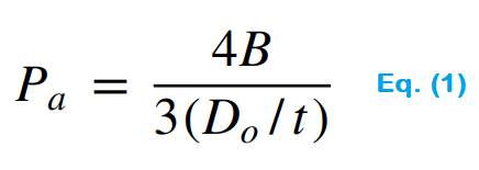
If the above condition met, Allowable External Pressure Pa can be calculated using the two equations below as per their conditions:
If the value of factor ‘B’ is determined, use below equation
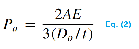
If the value of factor ‘A’ falls to the left of material or temperature curve and because of that value of factor ‘B’ cannot be determined, then go for the second equation below
Where,
Pa = Allowable external pressure
A = Factor determined from Figure ‘G’ in a sub-part of ASME Section II, Part D [to get the value of factor ‘A’ refer UG-25(c)(2) of ASME Section II, Part D].
B = Factor determined from the applicable material chart in sub-part 3 of ASME Section II, Part D [to get the value, refer to UG-20(c)].
E = Modulus of elasticity of the material at design temperature ( it is taken from the applicable materials chart in sub-part 3 of ASME Section II, Part D), interpolation may be made between the lines for intermediate temperature.
Now, let’s move to the second condition-
Condition 2: Pipes having Do/t values < 10
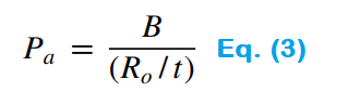
If the above condition met, Allowable External Pressure Pa can be calculated using the two equations below as per their conditions:
If the value of factor ‘B’ is determined, use below equation
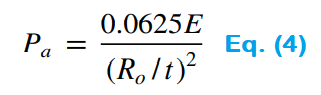
If the value of factor ‘A’ falls to the left of material or temperature curve and because of that value of factor ‘B’ cannot be determined, then go for the another equation below
Where,
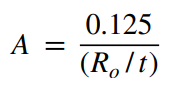
B = Factor B will be the same as the first condition, per UG-20(c)
Ro = Outer Radius of the Pipe
E = Modulus of Elasticity
Note: The second condition “Do/t values < 10” is very rare, in most of case we need to verify pipe wall thickness calculation for external pressure under the first condition “Do/t values ≥ 10″.
Okay! You are getting confuse right???
Don’t worry, we will solve the problem below to clarify all the doubts.
Inputs Required For External Pressure Pipe Thickness Calculation
We are considering a 34″ NPS Carbon Steel Pipe (ASTM A106 Gr. B) with 30.18 mm thickness (let’s consider this thickness is selected thickness under internal pressure)
- P = External Pressure = 20 psi
- Do = Outside Diameter of the pipe = 864 mm for 34″ NPS pipe (as per ASME B36.10M)
- L = Let’s assume an unstiffened (there is no stiffener in the straight section of pipe) length of the pipe = 14000 mm
- T = Selected pipe wall thickness as per internal pressure = 30.18 mm
- Mill tolerance = 0.3 mm
- Corrsion allowance = 3 mm
- t = [Selected Thickness (T) – mill tolerance – corrosion allowance] = 30.18 – 0.3 – 3 = 26.88 mm
- Design temperature = 150°C
- Y = SMYS (specified minimum yield strength) of the material = 220.63 MPa = 32000 psi
- E = Modulus of elasticity of the material at design temperature (150°C) = 28282358.9 psi (It is required only if the value of factor ‘A’ falls to the left of material or temperature curve)
Calculation Steps for Pipe Thickness Verification
Step 1: Calculate Do/t
Here,
Do = Outer diameter of pipe = 864 mm
t = 26.88 mm
So,
Do/t = 864/26.88 = 32.14 ≈ 32
Now, we can see Do/t is greater than 10, So this is meeting the first condition Pipe having Do/t values ≥ 10
Therefore, We will follow the calculation method of first condition
Step 2: Calculate L/Do, this will help to find the value of factor A
Here,
L = unstiffened length of the pipe = 14000 mm (you can get this information from piping layout)
So,
L/Do = 14000/864 = 16.20 ≈ 16
Step 3: Find the Factor ‘A’ from Figure ‘G’ of ASME Section II, Subpart 3, Part D
To find factor ‘A’ open the ASME BPV Code, Section II, Part D, Subpart 3 (Charts and tables for determining shell thickness of components under external pressure)
In subpart 3, go to Figure G, move vertically to see the value of L/Do, and move horizontally to see the value of Do/t. As per the calculated value match the both lines.
The matched point is circled with orange color in the below figure for better understanding, and the value of factor A is given at the downside of the figure (Refer the below figure).
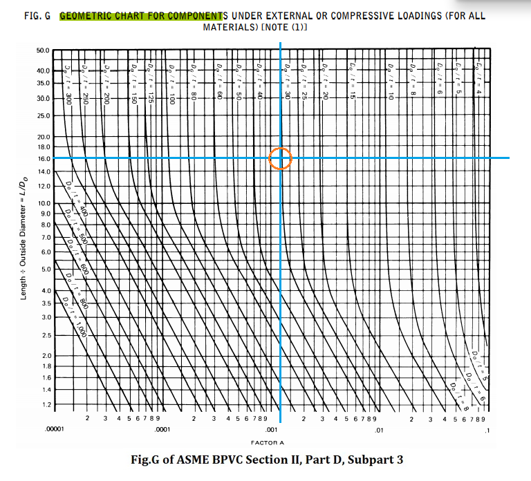
Therefore, from the fig. 1, The Factor A = 0.00140
Step 4: Now, Find The Factor ‘B’
Using the value of factor A (for our case A = 0.00140) and design temperature (150°C), we need to find the value of factor B.
Open the applicable material chart in subpart 3 of ASME BPV Code, Section II, Part D. As for our case pipe material is CS (carbon steel) with SMYS (specified minimum yield strength) = 32000 psi. So according to the pipe material and their SMYS value select the appropriate chart, for our case, we have to refer Figure CS-2 (refer the fig. 2 below).
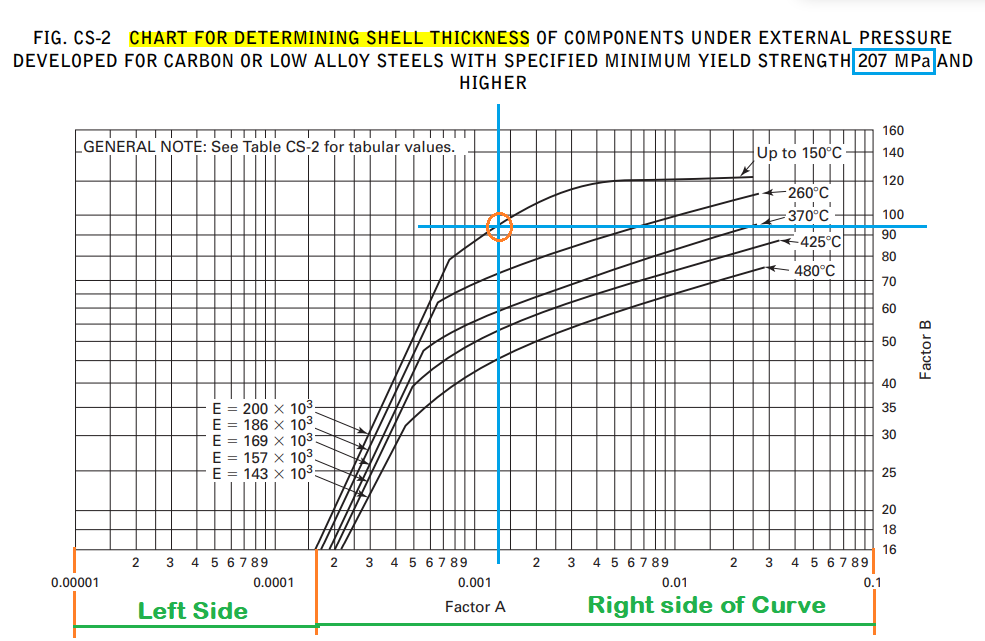
Here from the figure, we can see that the value of factor A is on the right side of the material or temperature curve.
So, it is clear that we will use Eq. (1) for calculating Allowable External Pressure.
Important Note: If the value of factor A would be at the left side of the curve then we will have to calculate allowable external pressure using Eq. 2 and Modulus of Elasticity (E) would be utilized in the equation.
Now, move horizontally to see the value of Factor A, select the curve according to design temperature (for our case it 150°C), and then match the lines. We can get the value of factor B on the right side of the chart (refer above fig. 2).
For this case, the value of factor ‘B’ = 94 MPa ≈ 13600 psi
Note: Same steps will be followed for the second condition also Pipes having Do/t values < 10, only the difference is Eq. 3 and 4 will be used instead of Eq. 1 and 2 respectively.
Step5: Calculate Maximum Allowable External Pressure (Pa)
Now, using the value of factor B, calculate the maximum allowable external working pressure (Pa) using the below equation:

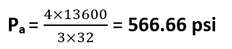
Since we see Pa (566.66 psi) > P (20 psi), It means the selected pipe wall thickness (T=30.18 mm) can withstand the external pressure exerted on the pipe and vacuum created inside the pipe.
If Pa < P, then need to increase the selected pipe wall thickness and follow the all steps again to verify the selected pipe thickness. This practice will be repeated until and unless the condition met Pa > P.
Few Related Posts
Pipe Thickness Calculation for Internal Pressure
A Presentation on Pipe Stress Analysis
A Presentation on Heat Exchanger
Some Important Piping Codes and Standards

Please give me some information about pipe size calculation for natural gas pipeline.
Means what minimum size of pipe used in pipeline if gas flow is given in MMSCMD unit.
Click here to see the steps for gas pipeline sizing
Good.
thanks for the knowledge sir.But i still have lots of question.is it only for calculate 1 straight pipe or one pipe spool?then,can u recommend engineering software for modeling vacuum flow inside pipe?thanks
Hi, Taufiq
The design length ‘L’ is the pipeline running centerline length between any two sections stiffened (support span length or joints span) in accordance with UG-29 means the length between the two flanges, heads, stiffeners, supports, etc.
Thank you Mr. Ahmad,
Do you have an example calculating thickness in accordance with ASME B 31.4, for an Hydrocarbon distribution line in airports?
Regards
I am trying to make a vaccuum kiln. My wish is for it to be 8-10′ long and 18-24″ round. I would prefer plastic for cost and weight issue, but steel is fine. I need to know how thick I need to go.
I am trying to get vacuum to 28 meters of mercury
Hopefully this answers the question you need.
did you get an answer to that question as im looking for the same info for a 24″ pipe
Please follow the steps mentioned in the article, you will get the answer.
Plz explain how to intrapolate
Tnx
Interpolation
Visit the above link to calculate the interpolation.
Thank you!
Hi Ahmad,
What is the standard/code reference of equation Eq(1) to Eq(4) ?
ASME BPV Code, Section VIII, Division 1, UG-28 through UG-30.
Hi,
What if the condition Do/t>10 is not met? How to proceed then? I have a 1500 pound pipe with thickness of 18,26 mm and Do=168,3 mm. Trying to learn more about this topic and how to demonstrate that vacuum is of no concern for a selected pipe.
I am sizing a vacuum line for 1.5″Hg, 400SCFM, 40′ long. Will a schedule 10 steel pipe handle the external pressure? Will a 12″ pipe have a pressure gain of less than 0.15″Hg?
hi, may i know why u decide the P to be 20 psi, i thought it should be 14.7 psi as the atmospheric pressure. Thanx!
can have a calculation sample for design temperature lower than 150 Degree C, let said 8- Degree C?
how to determine factor B in this case?
Hello , thanks for article.
In the example when to the left of curve then does the A factor from the chart also units of MPA, thus for equation 2, i.e need to convert to psi.
Important Note: If the value of factor A would be at the left side of the curve then we will have to calculate allowable external pressure using Eq. 2 and Modulus of Elasticity (E) would be utilized in the equation.
Is there any excel data available for this charts as calculating every time for every individual line is difficult
Hi Rehan,
Is Vaccum collapse calculation applicable for buried pipeline, in case yes. Equation( formulas) and fig/graph shall be same as described for piping .Is both the condition shall be considered cover depth of pipeline and as external force due to soil load + ATM Pr. (atmospheric pressure +external pressure due to soil load) .
Thanks, it’s very helpful, I’d like to know if there is any instruciton or guideline for plastic (polyethylene) pipe thickness calculation? I mean plastic pipe under external pressure or vaccum. Thanks for any help.
Can the pipe welding at every 12 meters (or 6 meters in case of single random length) be considered as stiffener as per ASME?
Hi Rehan,
I Found out that this article is very useful.
my question is:
1. How to decide mill tolerance 0.3 mm. Since Mill Tolerance for Thickness of Pipe is 12.5% from pressure design thickness. Why can’t we just multiply selected pipe wall thickness 30.18 mm times 0.875.
2. For Constanta Y (Specified minimum Yield Strength), is it get from Table A-1, ASME B31.3, or else.
Since if refer with ASME B31.3, I found out that the value is 35 Ksi (35.000 psi).
Thank you sir,