A Heat Exchanger is a device designed to transfer heat between two or more fluids (liquid, vapor, or gas) of different temperatures. On the basis of the heat exchanger, the heat transferring process can be gas-to-gas, liquid-to-gas, or liquid-to-liquid. The fluids are not in direct contact, unlike the distillation column.
This article focuses on the heat exchanger types, application, working, design codes, and exploring the various design considerations.
Table of Contents
Types of Heat Exchanger
There are mainly five types of heat exchanger used in the process industry-
- Double Pipe Type
- Shell and Tube Type
- Plate Type
- Spiral Type
- Fin-fan or Air Cooler
Double Pipe Type Heat Exchanger
The double pipe type heat exchanger is one of the simplest types of heat exchangers. It is called a double pipe type heat exchanger because one fluid flows inside a pipe and the other fluid flows over that pipe and inside of another pipe that surrounds the first pipe.
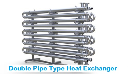
The construction of Double Pipe Type Heat Exchanger is a concentric tube type. The fluid flow in a double-pipe heat exchanger can be co-current or counter-current.
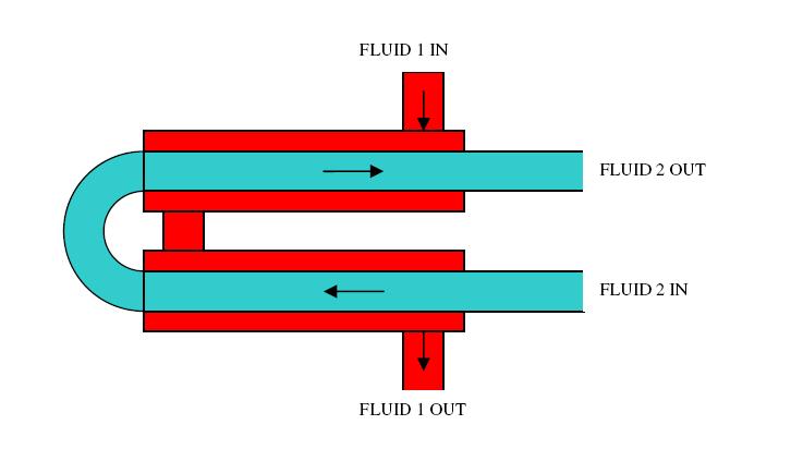
There are mainly two types of fluid flow patterns: co-current flow pattern is when the flow of the two fluid streams is in the same direction, counter-current is when the flow of the fluid streams is in opposite directions.
As the conditions (inlet temperatures, flow rates, fluid properties, fluid composition, etc.) in the pipes change, the amount of heat transferred also changes. This transient behavior of the fluid leads to a change in the process temperatures, which will push to a point where the temperature distribution becomes steady.
When the heat starts to be transferred, as a result, the temperature of the fluids changes until the temperatures reach a steady-state (means equal temperature in both fluids). Their transient behavior is dependent on time.
In the double pipe type heat exchanger, a hot process fluid (coming from the process equipment) flows inside the inner pipe and transfers its heat to cooling water flowing in the outer pipe. The heat transfer is kept going until conditions change, such as flow rate or inlet temperature.
The new steady-state will be observed once the inlet and outlet temperatures of the hot and cool fluid become stable. In practice, the temperatures will never be completely stable, but with major changes in inlet temperatures, a relatively steady-state can be observed.
Note: Double pipe type heat exchangers can be paired in series or in parallel to increase the heat transfer rate for a system without complication.
Fluid Allocation in the Inner Pipe or Outer Pipe
- Corrosive fluids are generally flowing through inner pipes, as if they flow through the outer pipe, they will corrode both the pipes.
- The steam is usually passed through outer pipes and cooling water in the inner pipes.
- If both liquids are equally corrosive or non- corrosive in nature, cold fluid is passed through outer pipes in order to reduce the heat losses.
Advantages
- It is one of the simplest and cheapest types of heat exchanger.
- It can be used for high temperature, high pressure, and highly viscous fluid services.
- It can be designed with longitudinal fins attached to the inner pipe to increase the heat transfer rate.
Limitations
- It provides less heat transfer area per unit length of the pipes as compared to other type heat exchangers.
- It can not bear the turbulency in the fluid flow through the pipes.
Application
- Polymer Industry
- Dairy Industry
- Chemical Industry
Before moving to other types of heat exchangers, let’s first understand the flow arrangement or pattern of the fluid in the heat exchanger.
Flow Arrangement or Pattern in the Heat Exchanger
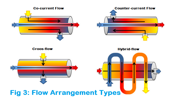
Flow Arrangement, also known as the flow pattern, of a heat exchanger, refers to the direction of movement of the fluids within the heat exchanger in relation to each other. There are four types of flow patterns-
- Co-current flow
- Counter-current flow
- Cross-flow
- Hybrid-flow
Co-current Flow
Co-current flow also known as parallel-flow is the flow arrangement in which the fluids move parallel to each other and in the same direction. Although this flow pattern typically results in lower efficiencies than a counter-flow arrangement.
Counter-current Flow
Counter-current flow also known as counter-flow is the flow arrangement in which the fluids move anti-parallel (means parallel but in opposite directions) to each other within the heat exchanger. This is the most commonly used flow pattern in the heat exchanger.
A counter-flow arrangement typically performs the highest efficiencies, as it allows for the greatest amount of heat transfer rate between the two fluids.
Cross-flow
In cross-flow arrangement, the fluids flow perpendicular to one another. The efficiency of this flow pattern type heat exchanger falls between the counter-current and co-current heat exchangers.
Hybrid Flow
In the Hybrid flow pattern, some combination of the above-mentioned flow arrangement is used. These types of flow patterned heat exchangers are typically used to accommodate the limitations of an application, such as space, budget, or temperature, and pressure requirements.
Figure 3, below, illustrates the various flow arrangement types-
Now, I hope you got an idea about the flow pattern or arrangement within the heat exchanger. Let’s move again to the other types of heat exchangers-
Shell and Tube Type Heat Exchanger
Out of all the types of heat exchangers, shell and tube type heat exchangers are the most versatile. A shell and tube type heat exchanger is designed with a number of tubes fixed on the tube-sheet placed inside a cylindrical shell.
The design of this type of heat exchanger allows flexibility to a wide range of pressures and temperatures. If we need to cool or heat a large amount of fluids or gases, the application of the shell and tube heat exchanger is an option to consider first.
A shell and tube type heat exchanger consists of a shell, tube bundle, tube sheet, baffle, tie rod, and two heads or caps at both ends of the shell. By selecting different design of these basic parts, we can have different types of heat exchanger as per TEMA.
Shell and Tube type heat exchangers are further classified on the basis of their design. There are mainly Four types-
- Fixed Shell and Tube Type
- U Tube Type
- Floating Head Type
- Kettle Type
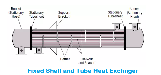
Fixed Shell and Tube Type Heat Exchanger
A fixed shell and tube type heat exchanger has straight tubes fixed on the tube sheet and welded at both ends to the shell.
Fixed tube Sheet heat exchangers are the ones that are very much used in process industries, as there is absolutely no chance for intermixing of the two fluids.
Main components of a Shell and Tube Type Heat Exchanger
The main components of a shell and tube heat exchangers are as follow:
- Tube bundle: The tube bundle is the set of tubes that provide the heat transfer area between the two fluids that circulate inside the tubes and the fluid that circulates inside the shell.
- Tube sheet: The tube sheet is a metal plate with a drilled hole, where the tubes are housed, which are fixed by expansion or welding.
- Baffles: The baffles are used to control the general direction of flow inside the shell and also provides supports to the tubes.
- Tie Rod: It is used to separate the two baffles.
- Shell and connections: The shell is the cylindrical envelope of the second fluid. The shell is generally made of a steel plate shaped cylindrical and longitudinally welded. The shell has nozzle connections for the inlet and outlet of the secondary fluid.
- Removable heads: The removable heads are connected to the tubular plates at both ends of the heat exchanger whose objective is to provide the circulation of the product through the tubular beam.
Applications
- The fixed shell and tube type heat exchanger is applicable to all services where the temperature difference between the shell and tube is small.
- It can be installed vertically and horizontally both ways.
Advantages
- The tubes can be cleaned mechanically after the removal of the bonnet.
- A wire brush can be used to clean the tube from inside.
- Rare leakage.
- Low cost
- Simple Construction
Limitations
- The tube bundle is fixed to the shell and cannot be removed.
- The shell can not be cleaned mechanically, need to clean with the chemical.
- Limited to the lower temperature.
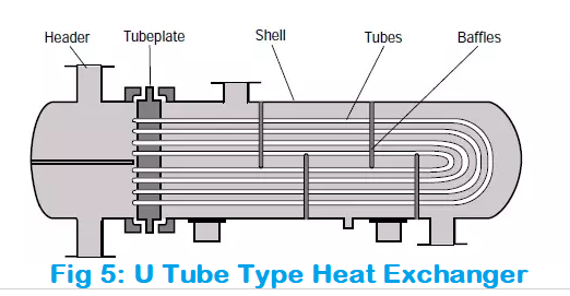
U Tube Type Heat Exchanger
As the name suggests, In this type of heat exchanger, the tube bundle is of “U” shaped. There is only one tube sheet as the tube is opened from one side only. All the tubes start from the upper half of this tube sheet and end within the lower half of the tube sheet, which makes a U-turn or U shape in the shell as shown in Figure 5, below-
Advantages
- Expansion of shell and tube is independent hence used for high-temperature services.
- It is possible to clean the shell from the inside by removing the tube bundle.
- Tube bundle cleaning is possible from the outside.
- Cost-effective, as expansion joints are not needed and the tube bundle is free to expand or contract.
Limitations
- Tube cleaning using the wire brush is not possible, as tubes are not straight.
- Removing the tube from the tube bundle is difficult.
- Installed only horizontally
Floating Head Type Heat Exchanger
In this type of shell and tube type heat exchanger, one end of the tubes is kept fixed in a tube sheet, while the other end of the tubes is free to expand or kept floating inside the shell.
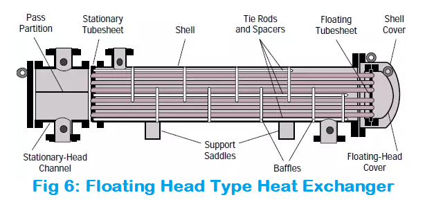
A floating head type heat exchanger is one of the most used heat exchangers. Generally, both the shell and tube bundle are free of expansion or contraction, which causes no thermal stress production between the shell and tube bundle, if the temperature difference between the two fluid is large.
Advantages
- Inspection is easy
- Expansion of tube and shell is not a problem
- Ease of Cleaning
- Accepted for the high-temperature application
- Suitable for the dirty fluid application, due to ease of cleaning
- High reliability and wide adaptability
- Tubes are straight, individual tubes can be replaced or cleaned without removing the tube bundle
- It overs comes the demerits of U tube type heat exchangers
- There is no limit for the number of tubes passes
Limitations
- It is costly compare to the other heat exchangers
- A large number of gasket joints
- Leakage may be a problem, unlike the U tube type heat exchanger due to floating head.
- Installed only horizontally
Kettle Type Heat Exchanger or Reboiler
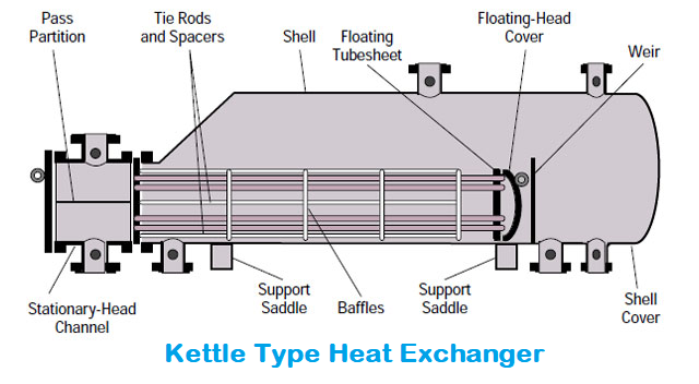
Kettle type heat exchanger mainly known as reboilers are used in the refineries within the distillation column assembly. It may require pumping of the distillation column bottoms liquid into the kettle, or there may be sufficient liquid head to deliver the liquid into the reboiler due to pressure head difference.
In this reboiler type heat exchanger, steam flows through the tube bundle and exits after getting condensate. The liquid from the bottom of the tower, commonly called the bottoms or bottom product flows through the shell side.
Kettle reboilers are reliable enough that they can handle high vaporization of up to 80% and are easy to maintain this level. It produces chemical vapor. The bundle of kettle type reboiler may of U tube type or floating head type.
Difference Between Reboiler and Boiler
| Parameters | REBOILER | BOILER |
|---|---|---|
| Purpose | Produce Chemical Vapor | Produce Steam |
| Equipment Type | Process Equipment | Utility Equipment |
| Location at Plant | Process Plant | Utility Area |
| Heating Medium | Steam | Fire |
| Design Code | TEMA-R | IBR (Indian Boiler Regulation) |
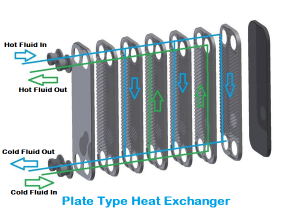
Plate Type Heat Exchanger
A plate type heat exchanger is made of a series of parallel plates that are placed above the other plate (alternatively) so as to allow the formation of a series of channels for fluids to flow between them.
The gap between two adjacent plates creates the channel in which the fluid flows. You can increase or decrease the capacity of the heat exchanger by adding or removing the plates whenever required.
Inlet and outlet holes at the corners of the plates allow hot and cold fluids to flow through alternate channels in the exchanger so that a plate is always in contact on one side with the hot fluid and the other with the cold fluid.
The size range of a plate is recommended from a 100 mm x 300 mm up to 1000 mm x 2500 mm. The minimum number of plates is recommended in a single exchanger is 10 and the maximum can be several hundred.
The below figure shows the flow of fluids inside the plate type exchanger. Fluids are divided into several parallel streams and can produce a perfect counter-current flow.
Advantages
- High Heat Transfer area and rate
- Compact Design and lower floor space requirement
- By increasing the number of plates, the heat transfer area can be increased
- Suitable for lower flow rate and heat-sensitive substances
- Lower liquid volume required
- Low Cost
- Lower heat losses
- Ease of maintenance
Limitations
- Limited to 150°C (for low-temperature application) and 300 psi pressure
- Leakage is more as compared to other types of heat exchangers
- Not suitable for high viscosity application
- The sump is required to collect the liquid between the plates
- The gasket used between the plates can not handle corrosive fluid
- Pressure drop is higher
Spiral Type Heat Exchanger
The spiral type heat exchanger is manufactured by rolling two metal plates around a central core to generate two concentric spiral flow passages, one for each fluid. The plate edges are welded in a manner so that each fluid stays within its own passage and there is no bypass flow or intermixing of both fluids.
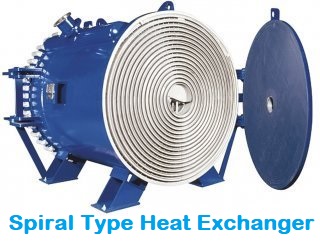
Channel plate width and the gap between plates are optimized for the specified duty, maximum heat transfer rate, and ease of access. The plate gap is maintained by a welded spacer, although some exchanger do not require them.
Due to its circular design and large surface area to volume ratio, the spiral heat exchanger offers unique advantages over other types of heat exchangers.
Advantages
- Higher Thermal Efficiency
- Self-Cleaning capacity for Passages
- Counter-current or Co-current flow pattern
- Less space required
- Lower cost
- Less maintenance required
- Longer Operation duration is possible
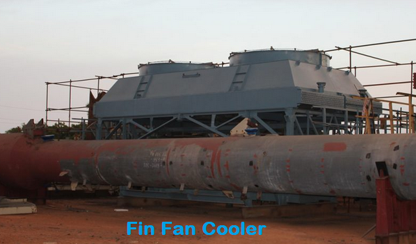
Air Cooler or Fin-fan Cooler
The Air Cooled Heat Exchangers also known as Fin fan Cooler is nothing but the traditional name of Air Cooler. For example a radiator in the car. Although the Fins are used in the Cooler, it increases the residual time, which further increase the efficiency of the system. In this type of heat exchanger the ambient air used as the cooling medium.
Application
- Used in overhead line of distillation column for cooling of the top product
- Used in a chiller to remove heat from condenser
- Mounted on pipe rack or may be on platform or structure
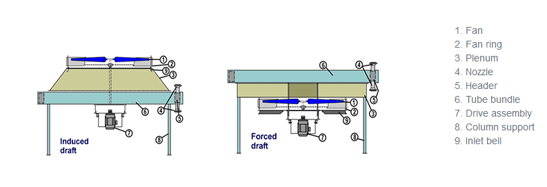
Fin Fan Cooler further classified in two types-
- Induced Draft
- Forced Draft
Difference Between Induced and Forced Draft Heat Exchanger
| Induced Draft | Forced Draft |
|---|---|
| Fans are positioned above the tube bundle | Fans are positioned below the tube bundle |
| It creates Vacuum | It creates Pressure |
| Lower operating cost | Higher operating cost |
| Space requirement is more | Less space requirement |
| Most preferred type | Used only if the space is problem |
Refer below figure for better understanding
Heat Exchanger Selection Considerations
There are a wide range of heat exchangers available in the market or can be manufactured, the suitability of its type and design in transferring heat between fluids is dependent upon the specifications and requirements of the application. The calculation is done for the sizing of heat exchanger per the heat transfer rate requirement and some other consideration is taken for the selection of heat exchangers.
Some of the factors that the respective professionals should keep in mind while designing and choosing a heat exchanger-
- Type of fluids, stream, and their properties
- The required thermal outputs
- The availability of space
- Temperature range
- Project Budget
- Vendors availability
- Statutory Requirement
- Design code
- Application, etc.
Design Code Associated with the Heat Exchanger
The design code used for manufacturing heat exchanger is mentioned below-
TEMA (Tubular Exchanger Manufacturing Association)
TEMA is further categories on the application basis of heat exchangers-
- TEMA-R: If the heat exchanger is used in petrochemical, refineries or hydrocarbon industry
- TEMA-C: If the heat exchanger is used in general services
- TEMA-B: If the heat exchanger is used in chemical services
ASME (American Society of Mechanical Engineers)
- ASME Section II
- ASME Section V
- ASME Section VIII
You can watch the below video to feel the object
Few Related Posts
Some Important Piping Codes and Standards
Miter Bend Calculations For Fabrication Purpose
Pipe Welding Positions: 1G, 2G, 5G, and 6G
Pipe Thickness Calculation for Internal Pressure
References
www.enggcyclopedia.com
www.thomasnet.com
Heat Exchangers: Selection, Rating, and Thermal Design Book by Anchasa Pramuanjaroenkij, Hongtan Liu, and S. Kakaç
Heat Exchanger Design Handbook Book by Kuppan Thulukkanam
www.onda-it.com
unitedcoolingtower.com
www.chartindustries.com


can you please share with me which are the best heat exchanger manufacturers?