Miter Elbow or Miter Bend is a Fabricated Fitting used to change the pipeline direction. The Standard Fittings (Wrought Elbows) are not easily available and economical for the larger sizes.
Miter elbows are made up through fabricating the numbers of pipe cut pieces and it includes numbers of the weld joint. So, the design engineer needs to design it carefully, as the more numbers of weld joints the weaker the components, and if the numbers of weld joints are less, the pressure drop will be higher.
In this article, we will learn, how to decide the numbers of miter joints or miter pieces of the miter bend or miter elbow? what should be the minimum pipe thickness required to fabricate the miter bend? The required length and weight of the pipe to prepare miter elbow.
Table of Contents
Formulas Used For Miter Bend or Miter Elbow as per ASME B31.3
Here, we will see the calculations for design purpose, click here If you want to learn miter bend calculation for fabrication purpose, Let’s see below the formula for miter bend design as per section 304.2.3 of ASME B31.3
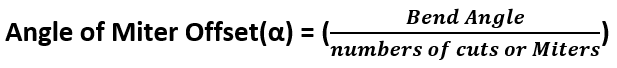
Angle of Offset for Miter Bend
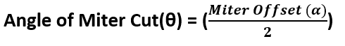
Angle of Cut for Miter Elbow
Maximum Allowable Internal Pressure (Pm)
There are two cases for maximum allowable internal pressure of miter bend-
- Single Miter Bend
- Multiple Miter Bend

Single Miter Bend
For single miter bend there are two conditions:
1. Angle of Cut(θ) ≤ 22.5°
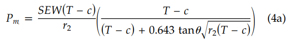
If the above condition met, use the below equation (4a) of section 304.2.3

Where,
Pm = Maximum allowable internal pressure
S = Allowable stress for pipe material
E = Quality factor for longitudinal weld joints in pipes
W = Weld joint quality reduction factor
T = Ordering thickness of the pipe as per PMS (Piping Material Specification) or You can calculate the pipe wall thickness click here to see the complete steps for pipe thickness calculation
C = Sum of mechanical, corrosion, and erosion allowances
θ = Angle of the miter cut
r2 = Mean radius of the pipe = (D-T)/2
D = Outer diameter of the pipe
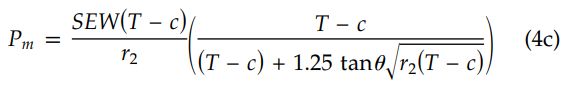
2. Angle of Cut(θ) ≥ 22.5°
If the above condition met, use the below equation (4c) of section 304.2.3
Important Note: Single Miter Bend is rarely used, as it is not safe and reliable. In most of the cases, multiple miter bends are used.
Multiple Miter Bend
For multiple miter bend, we need to find maximum allowable internal Pressure two times using two different equations:
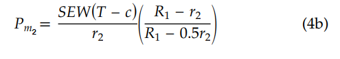
Where,
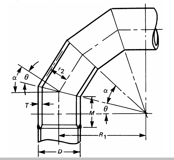
R1 = Radius of the miter bend, refer the fig. 1
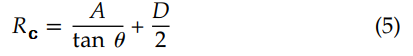
Here, we will be required to cross-check, whether the selected radius (R1) of miter bend is greater than the calculated radius (Rc) of the miter bend using the below equation (5). If the selected radius (R1) is smaller than the calculated radius (Rc), then we will have to increase the selected radius (R1) until it is greater than the calculated radius (Rc).
Note: The selected radius can be 1D, 1.5D, 2D, 3D, 5D, 7D, etc.
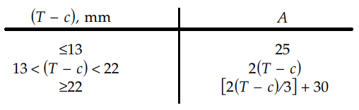
To get the value for A, Check the below table 1:
Crotch Length (M)
This length is required to calculate only if the ordering thickness of the pipe (T) is not enough to withstand the design pressure and temperature of the line. If the ordering thickness is not enough then we increase the thickness of the pipe and need to keep increasing until and unless it passes for the design pressure and temperature of the line.
Calculation Steps:
We required to follow the below calculation steps for miter bend or miter elbow design-
- Select the pipe from the PMS(Piping Material Specification- it includes pipe size, type, thickness, and material) or you can calculate the thickness as per the design condition
- Start calculating maximum allowable internal pressure (Pm) for multiple miter bend using equation (4a), need to start with 2 numbers of the miter.
- Check that if the maximum allowable internal pressure (Pm) > Design pressure of the line (Pdesign), if not, need to increase the numbers of the miter to 3,4 & 5 (maximum), and again calculate Pm with the increased numbers of the miter, and check again whether Pm > Pdesign.
- If it passes the condition “Pm > Pdesign” then that number of miter at which it passed, will be the required minimum numbers of the miter for miter bend of that specific line, and that thickness of the pipe will be the minimum required thickness (means the same pipe used for that line, can be used for fabricating miter bend).
- If even with 5 numbers of the miter, the condition “Pm > Pdesign” is not met, then increase the next available thickness of the pipe in the ASME B36.10 M or ASME B36.19 as per the pipeline material type, and recalculate the Pm with the new thickness and minimum numbers of the miter, and keep increasing the numbers of the miter until it passes the condition “Pm > Pdesign“.
- Repeat steps 4 and 5, until the condition “Pm > Pdesign” is met with the minimum numbers of the miter and minimum thickness.
- Calculate Rc using equation (5).
- Make sure that the selected radius (R1) of miter bend is greater than the calculated (Rc) of the miter bend, If not, then increase the selected radius (R1) to meet the required condition “R1>Rc“.
- Now calculate Pm2 based upon the Final selected radius (R1) to see Pm2 > Pdesign, use equation (4b) for this calculation.
- If the thickness has been increased (means the thickness of the pipeline and thickness of the pipe used to fabricate is different) then we need to calculate crotch length (M), the formula is mentioned above in the formula section, M should be in multiples of 5.
Okay! getting confused???
Don’t worry, we will solve a problem to clarify these steps and the uses of the formula below:
How to Decide Numbers of the Miter or Miter Cuts or Miter Pieces or Miter Segments and the Minimum Pipe Thickness Required for the Miter Bend?
Okay! to get this answers, let’s solve a problem:
Case Study for Miter Bend Design Calculations
Input Required
Line Size = 12″ NPS
D = 323.8 mm
Pipe Material = A106 Gr. B
Pipe Type = Seamless
Pdesign = 285 psi
S = 20000 psi
E = 1
W = 1
T = 6.35 mm (SCH20)
Mechanical Allowance = 12.5%
Corrosion Allowance = 3 mm
C = Mechanical allowance + corrosion allowance = 0.79+3 = 3.79 mm
(T-C) = 2.55 mm
R1 = 1.5D = 1.5x12x25.4 = 457.2 mm
r2 =(D-T)/2 = (323.8-6.35)/2 = 158.72 mm
Bend Angle = 90°
Solution:
Put the given value in equation (4a)

Where,
θ = (Bend Angle/Numbers of Miter or cut) / 2 = (90°/2) / 2= 22.5°
Therefore,
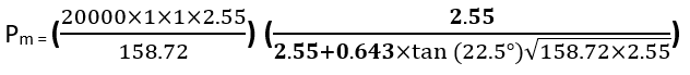
Pm = 103.60 psi
We can see Pm< Pdesign
So, increase the numbers of the miter to 3 and recalculate (only the value of θ (15°) will be changed, rest will be the same.
Now,
Pm = 136.19 psi
Still,
Pm< Pdesign
Similarly, for 4 miters, (θ =11.25°)
Pm = 159.93 psi
Still,
Pm< Pdesign
Similarly, for 5 miters, (θ =9°)
Pm = 178.16 psi
Still,
Pm< Pdesign
Here, we can see after taking the numbers of the miter to 5, still Pm< Pdesign, as per ASME B31.3, it is recommended to use a maximum of 5 miters or miter cuts.
So, now we will have to increase the pipe thickness to withstands the design pressure (Pdesign = 285 psi) but also need to check the minimum numbers of the miter required for that increased thickness.
Check the next thickness available in the ASME B36.10M
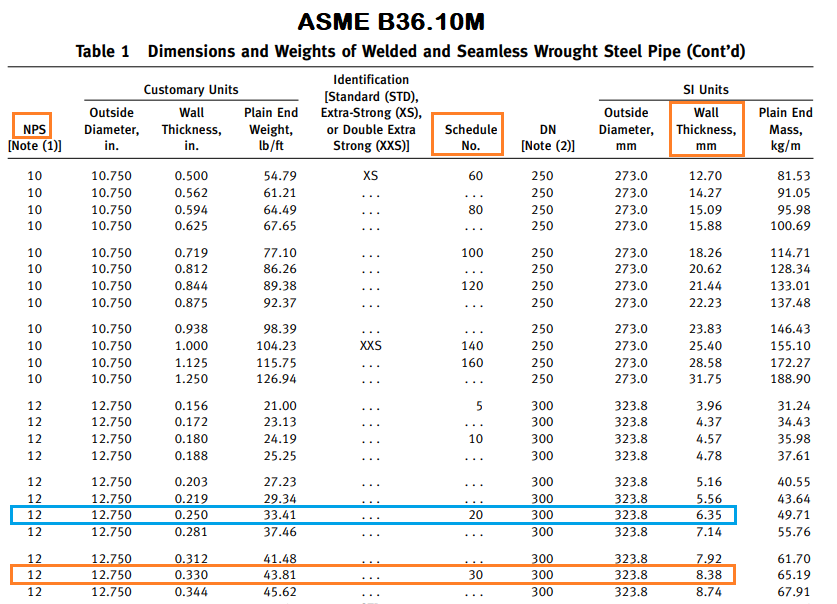
By referring to the above fig. 3, we can see pipe thickness for 12″ SCH30 is 8.38 mm, the next thickness is 7.14 but we are taking 8.38 mm because the pipe is seamless and for seamless pipe, we move schedule to schedule, which means the first thickness was 6.35 mm SCH20, so the next thickness will be 8.38 mm SCH 30.
Quick Calculation Hack: To check with less effort, start calculating Pm with 5 miters, and if it is passing the conditions “Pm> Pdesign” then calculate Pm for 4,3, & 2 numbers of the miter to check the minimum numbers of the miter required.
If Pm< Pdesign then go with the next thickness directly, no need to calculate for 2,3, & 4 numbers of the miter for the same thickness.
Let’s apply this hack to the next calculation:
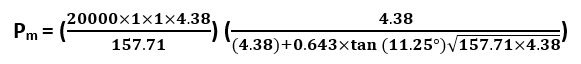
Now we have the next thickness = 8.38
Here, r2 will also be changed with the change of pipe thickness:
r2 = (D-T)/2 = (323.8-8.38)/2 = 157.71 mm
Start calculating with 5 numbers of the miter (θ =9°)
(T-C) will be now = (8.38-(3+1) = 4.38 mm
Therefore,

Pm = 344.76 psi
Now, we can see Pm> Pdesign, which means the minimum thickness required to fabricate the miter bend will be 8.38 mm, SCH20
Now, we need to find the minimum numbers of the miter or miter cuts (θ =11.25°) required to fabricate the miter bend for our case.
So, let’s calculate Pm for 4 numbers of the miter to check whether it can pass or not.
Pm = 314.26 psi
We can see Pm> Pdesign for 4 numbers of the miter as well
similarly for 3 numbers of the miter (θ =15°)
Pm = 273.10 psi
Here, we can see Pm< Pdesign (means it fails at 3 numbers of the miter)
So, we are now clear that the minimum number of the miter required is 4
Now, we need to check whether the selected radius (R1) of the miter bend or miter elbow is greater than the calculated radius (Rc)
For our case, the selected radius of miter (R1) is 1.5D = 457.2 mm
Calculate (Rc) to compare it with (R1)
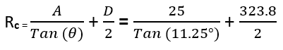
The value of A can be found above in Table no. 1
Therefore,
Rc = 287.58 mm
We can see R1 > Rc
Now, Calculate Pm2 (maximum allowable internal pressure based on the miter bend radius) using the equation (4b)

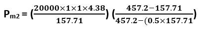
Pm2 = 439.68 psi
We can see Pm2 > Pdesign
It is also clear from the above calculation that the selected miter bend radius (R1=1.5D) is accepted and no need to increase the miter bend radius or miter elbow radius
As discussed in the calculation step: 10, if the thickness is increased then we are required to calculate crotch length (M)
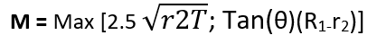
We know from the formula,


M = Max [90.88 ; 59.57]
So,
M = 90.88 mm (it should be multiple of 5, for safe allowance) ≈ 90 mm
Outputs from the Calculations
Following are the outputs from the above calculations:
- Minimum pipe thickness required for miter bend = 8.38 mm (SCH30)
- Minimum numbers of the miter or miter cuts required for miter bend = 4
- The angle of Cut (θ = 11.25°)
- The radius of Miter Bend ( R1= 1.5D = 457.2 mm)
- Crotch Lenght (M = 90 mm), it is required only if the thickness is increased. If the thickness is not increased then M = 2Dtan (θ)
All this calculation is for design purposes, only after getting this required data miter bend is fabricated. For fabricating the miter bend or miter elbow some calculations are required. Click here to see the Miter bend Calculation for Fabrication Purpose
Required Pipe Length for Miter Bend or Miter Elbow
As per the numbers of the miter or miter cut, draw a sketch as below-
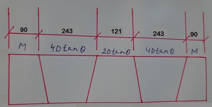
We have all the required values now, put in the formula and we can get the total length
Where,
M = Crotch length =90 mm
D = Outside diameter of the pipe = 323.8 mm
θ = Angle of cut = 11.25°
Therefore,
L = 90+243+121+243+90+20 (taking 5 mm per cuts cutting allowance, cutting allowance depends upon the cutting method used)
L = 807 mm
Weight of the Pipe
Open ASME B36.10M to check the weight of the pipe, you can refer to the above fig. 3
The weight for 12″ NPS (SCH30) is given 65.19 kg/m
Convert the pipe length into the meter (L = 0.807 m)
Now, multiply weight with length
So, the pipe weight for the Miter Elbow or Miter Bend = 65.19 × 0.845 = 52.6 kg
You may also like to read
A Presentation on Heat Exchanger
Some Important Piping Codes and Standards
Pipe Thickness Calculation for Internal Pressure
Pipe Rack Design and Calculations
Hydrotest Procedure for Piping system

I am in the Pipeline fabrication profession, I have worked in India and outside India as well.
Wow
How have you got a mechanical allowance of 0.79?
12.5% of 6.35mm will be 0.79 mm.
It’s just an example, it can vary from case to case.
R1 value we need to calculate by 1.5*25.4*NPS
= 1.5*25.4*12
= 457.2mm
Is my answer is correct?
Yes K.P., You are absolutely correct.
up to 12″, D= Pipe Size x 25.4 mm
and above 12″, D= Pipe Outer diameter (mm)
For example- for 14″ NPS
R1 = 1.5 x Pipe Size x 25.4 = 1.5x14x25.4 = 533.4 mm
R1 = 1.5xPipe Outer diameter = 1.5×355.6 = 533.4 mm
We can see here by both methods, the answer is the same.
I will update the post, as we are using 12″ NPS in our example.
Thanks for your feedback.
1.5d or 2d elbo hite plas mainas
That’s Awesome Rehan …Kudos to you !!
Thanks, Vrishal for your deep reading and for providing valuable feedback.
can we cut the miters from welded pipe with circumferential joints already existing in it? reference standard any?
Hello.
How do you calc with full vacuum conditions?
Thank you.
thank you sir….
Can you post about pipe schedule, NPS and standard
While solving the case study, you should have used equation 4c for first case where angle Theta is 22.5 since 4C is used when Theta is equal to or more than 22.5 Degree. Thereafter, when 4c is not satisfactory, and angle theta decreases less than 22.5 degree, you could have switched to equation 4a/4b.
Did I interpret it right?
Hi Rehan, could you please explain where the terms ‘4Dtanθ’ and ‘2Dtanθ’ originated in the calculation of pipe length for miter bend fabrication?
Hi Rehan, The content given by you is very easy to understand and thanks for the same. I have 1 query about M dimension. As per Asme B31.3 304.2.3 (c) “The mire wall thickness T used in equation (4a), (4b) & (4c) shall
extend distance not less than M from inside croth of the end mitre weld.”
Query 1: What is the relation of thickness T with ditance M? How to extend thicness T by distance M?
As per your sample calculation it is mentioned that “As discussed in the calculation step: 10, if the thickness is increased then we are required to calculate crotch length (M)”.
Query 2: I could not correlated this statement with paragraph given in Asme B31.3 304.2.3 (c). Can you elaborate the content given in your sample calculation.
Contact no : 9558805607