Expansion loops are one of the most effective ways to increase the flexibility in the piping system. The stress is generated in the pipelines due to thermal expansion or contraction and it can be damped by the arms of the loops mounted vertically to the mainline.
Section 319.7 of ASME B31.3 tells that the expansion loops or expansion joints are the most common items used in the industry to absorb the thermal expansion of the pipe. The expansion loops required larger spaces over expansion joints, Although, the expansion joints are not as reliable and long-lasting as expansion loops especially when they are exposed to a particular level of torsional loads frequently.
In this article, we will mainly talk about the expansion loops, but before moving to the expansion loop, take a brief view of thermal expansion, why does it take place in the piping system, and how to calculate it.
Table of Contents
What causes thermal expansion?
Change in temperature causes an object to change its shape, area, or volume. Pipes generally expand when heated, and contract when cooled. This happens because the molecular structure of the pipe material starts expanding due to the increased kinetic energy at a higher temperature, which causes the molecules to move around more.
The rate of thermal expansion mainly depends on three factors:
- The pipe material: Different materials expand or contract at different rates. So the different types of pipe will have different coefficients of expansion. Therefore, it is necessary to calculate the rate of pipe expansion on each individual type of pipe being installed.
- The length of the pipe: The longer the pipe run, the more expansion or contraction will occur.
- The minimum and maximum temperature: The temperature range that the pipe will be exposed to, or in other words, the difference between the temperatures of the pipeline at the idle and operating conditions.
How to Calculate the Expansion in the Pipe
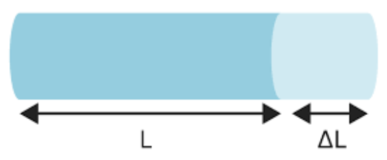
To make the piping system flexible enough, the piping engineer must know the expansion or changes in length (ΔL), the pipeline will occur during operating conditions.
We know from literature,
ΔL = α×L× ΔT
Where,
α = thermal expansion coefficient {(mm/mm/°C ) × 10-6}
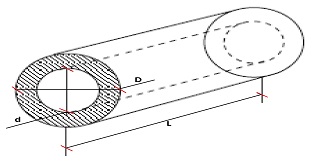
L = original length of the pipe (m)
ΔT = (T2-T1) change in temperature (°C)
Note:
- Thermal expansion/contraction coefficient is provided in Table C-2, Appendix C, ASME B31.3
- The coefficient values in minus represent contraction and the positive values represent the expansion of the pipe.
Now, Let’s move to the expansion loops:
Positions of Expansion Loop
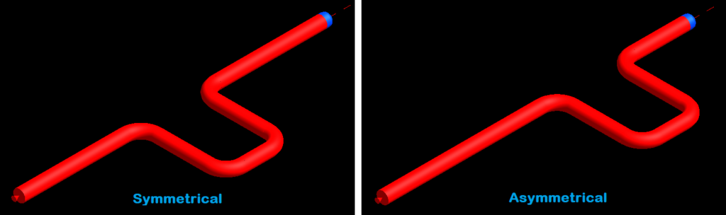
The thermal expansion loops can be symmetrical or asymmetrical in terms of their position in between the anchors or fix supports. The symmetrical expansion loops are more effective as they damp the stress equally from both sides. However, the asymmetrical expansion loops are also used commonly in the field depending on the space availability of pipe ways or to utilize existing loop spacing.
3D VS 2D Expansion Loops
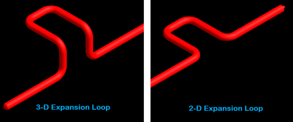
3D loops are preferred because they prevent possible conflicts with
the other lines and do not disturb the basic design of the new line to be routed. In these kinds of expansion loops, the height of the rising arm depends upon the particular application, as it can vary from project to project.
The vertical arms in the 3D expansion loops are very functional and they reduce the overall stress level in the elbows as well as simplifies the loop’s design. On the other hand, the 3D expansion loops do not contribute to the flexibility of the mainline as they do not change the position of the center of gravity with respect to the baseline.
Note: Some lines are restricted to use 3D expansion loops.
- Any line with slope
- Flare Header, etc.
Design Considerations for Expansion Loops
Following are the major points to be considered while designing the expansion loop:
- The line exposed to the maximum thermal expansion due to process conditions is located in the most outer position in the pipe rack for ease of supporting.
- Whereas, the lines exposed to the lower thermal expansions can be positioned in the inner positions on the pipe rack.
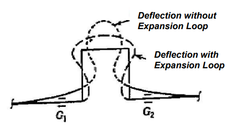
- The guide supports mounted on both sides of the expansion loop, G1 and G2 as shown in the below figure, have an important role in the functionality of the loop. The elbows can slip through the axis of the mainline instead of slipping laterally.
- The two pipelines may collide after thermal expansions If the space between the lines is not being designed adequately. In order to defeat this problem, the spacing between the adjacent pipes shall be bigger than the expansion differences between the two lines.
- Vertical loops may be placed at road crossings instead of horizontal loops.

Calculation of Minimum Required Length of Expansion Loops
In order to calculate the minimum required expansion loop length, there are two common methods:
- Calculating with Nomogram
- Calculating with Kellogg’s Chart
The total length of the expansion loop consists of, 1 width (W), 2 lengths (L), and 2 heights (H) if it is a 3D expansion loop.
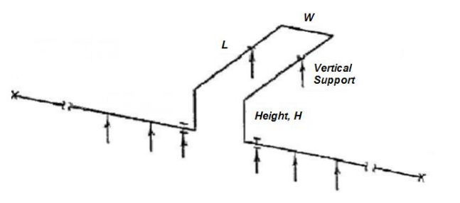
The equation below for the total length of the loop (LL) in terms of arm geometry is shown below:
LL = W+2L eq.(1)
The L/W ratio is specified normally in the literature as below:
L = 2W eq.(2)
From equation (1) and (2), we can get:
LL = 5W eq. (3)
To learn in more detail, you can enroll for the upcoming course “Fundamentals of Pipe Stress Analysis” by Stressman Engineering in partnership with EngineeringTrainer.com
Calculating with Nomogram
The nomogram is used with the above equations to find the details of the loop such as width and length:
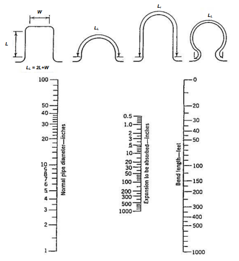
- In the nomogram above, there are 3 vertical scales available:
- Left Scale: Outer diameter of the pipe, D, (inches)
- Middle Scale: Expansion to be absorbed ΔL, (inches)
- Right Scale: Total length of the loop, LL, (feet)
Calculating with Kellogg’s Chart
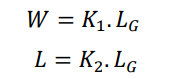
The designer of the thermal expansion loop should select one of the K1 or K2 values from the below chart with respect to the physical conditions at the site. The value to be read in the y-axis of the chart and they are used to determine the loop width, W, and the loop length, L, values.
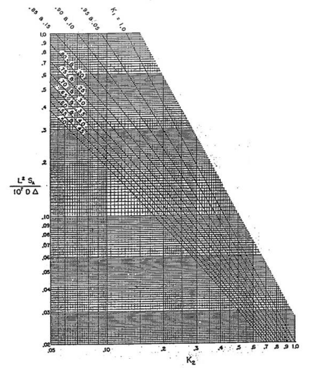
The values of K1 and K2 to be used in the above chart are the inverse ratios of the distance between the guide supports and the loop width & length respectively:
Note: The methods for calculating the expansion loop length may vary from company to company.
Advantage of the Expansion Joints Over Expansion Loops
- Expansion loops required a very large space.
- The pressure drop in line is higher due to multiple application elbows in the expansion loop.
- There is no adequate support structure required to support the size, shape, and weight of an expansion loop.
- The expansion loops are ineffective to use in the application of low pressure or large diameter lines.
- The construction and installation of the expansion loops require high man-hours.
- In most cases, using expansion joints is more economical than using expansion loops.
You may also like to read
Reinforcement Pad Calculation for Branch Connection
Miter Elbow or Miter Bend Design Calculations
Pipe Wall Thickness Calculation For External Pressure or Vacuum
How to Decide Flange Rating for Piping System?
A Presentation on Pipe Insulation

What is the best distance between the first guide and the expansion loop?
Hello Mrt,
Generally, the distance between the center point of the expansion loop and the center point of the guide support is taken as 2L. But, it can vary from company to company or from project to project.
May use guide cantilever method for find ideal first guide support location.
sir I have a query
why in some place in piping, loop are vertical up ,vertical down and insome place horizontal