The following article will provide a sample case study for Storage Tanks Layout or Tank Farm based on OISD-Standards-118. It will also cover dyked enclosure calculations including required dike wall height.
Before moving further, I want to make sure you have already read the previous article on Tank Farm Design Considerations. If you have not read yet, please take a view on it, as it’s going to help a lot with our case study.
Let’s assume that the following inputs are received from the client for the tank farm design or storage tanks layout.
Table of Contents
Inputs received from the Client
| TANK TAG NO. | STORAGE CAPACITY | TANK HEIGHT | TANK DIAMETER | PETROLEUM CLASS of Storage Product |
|---|---|---|---|---|
| T1 | 425 m3 | 9.6 m | 7.5 m | CLASS-B |
| T2 | 450 m3 | 9 m | 8 m | CLASS-A |
| T3 | 400 m3 | 9.3 m | 7.4 m | CLASS-B |
| T4 | 380 m3 | 9.1 m | 7.3 m | CLASS-B |
| T5 | 455 m3 | 9.7 m | 7.7 m | CLASS-A |
| T6 | 700 m3 | 12.5 m | 8.5 m | CLASS-C |
| Total | 2810 m3 | NA | NA | NA |
Notes:
1. Foundation Height for all the Tanks are 400 mm
2. Foundation Diameter for all the Tanks are Tank diameter + 500 mm
3. The Shape of all Foundations is circular and without a shoulder.
3. All the Storage Tanks are of Conical Type.
Now as per the above inputs, the below points can be decided based on OISD-Standard-118 and design considerations discussed here.
Let’s see the decided actions below:
Decided Actions Based on OISD-Standard-118
- The aggregate storage capacity of all the six tanks does not exceed 5000 m3 and the diameter of the largest tank of the group does not exceed 9 m. Hence, firewalls are not required for our case.
- The storage capacity of the largest tank (T6) of the group does not exceed 50000 m3. Therefore, there will be two rows of storage tanks in the dyke enclosure or Tank Farm.
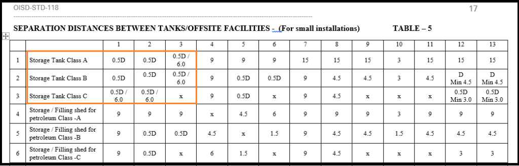
- The separation distances between the tanks will be in accordance with Table-5 of OISD-standard-118 as they are the small installation (the aggregate capacity and diameter of the largest tank (T6) do not exceed 5000 m3 and 9 m respectively.
- The separation distances between the tanks storing Class-A & Class-B petroleum products will be 0.5D and for tanks storing Class-A & Class-C or Class-B & Class-C petroleum products will be 0.5D or 6 m (whichever is minimum will be considered).
Note: Always take the diameter of the larger tank for separation distance calculation. - The minimum distance between the tank’s outer shell and the inside surface of the dyke wall will be 0.5H (where H is the tank height).
- The roof of all the tanks is of fixed type and the aggregate capacity of all the six tanks does not exceed 60000 m3. Therefore, all the tanks will be installed in only one Dyke Enclosure.
Arrangement of the Storage Tanks
Let’s follow the below steps to arrange the tanks in a proper manner:
- As per OISD-Standard-118, we should prefer to install the Class-C petroleum product storage tanks in a separate dyked enclosure. But, in our case, there is only one tank that is storing Class-C petroleum products. Therefore keeping in the cost, we are keeping all the tanks in a single dyked enclosure. But, we will have to follow the safety rules as per the Class A & Class-B petroleum product.
- There will be two rows of tanks each of 3 tanks. Please refer the Fig. 1 below.
- Allocate the largest Tank (T6) from the group at any corner of the Tank farm. Note: Larger in terms of diameter.
- Locate the smallest tank (T4) next to the largest one (T6) at any side with free space (either in row or column).
- Position the second smallest tank (T3) next to the largest tank (T6) where the free space is available either in row or column.
- Now, put the second-largest tank (T2) next to the smallest tank (T4).
- We will have to arrange the rest left tanks in the same manner as arranged above, one smaller and one larger alternatively.
- By implementing the above steps for allocating the tanks, we can find the shortest required Length & Width of the Tank farm.

Separation Distances between the Storage Tanks
From the below Table-5 of OISD-118, we can get the formula for separation distance calculation, and applying it we can get the minimum required distance. These points are already discussed above in point number 3 and 4 of “Decided Actions Based on OISD-Standard-118“. The calculated result can be seen in Fig.1 above.
After allocation of the tanks and separation distances calculation, the following steps should be followed:
- Now, calculate the total length of each row and width of each column with the presented distances in Fig. 1.
- For our case L1=42.80 m, L2=40.10 m, W1=30.80 m, W2=28.50 m, W3=28.70 m.
- Select the longest length and width amongst all calculated lengths and widths. For this case, L (longest length) =42.80=43 m and W (wider width) =30.80=31 m.
- Now, the differences in length L & L1 and L & L2 need to adjust in length L1 and L2 for final adjustment. These changes in mentioned in Fig. 2 below.
- Similarly, the differences in width W & W1, W & W2, and W & W3 needs to adjust in width W1, W2, and W3 for final adjustment.
- After the final allocation and adjustment of the distances between the tanks & inner surface of dyke wall and the tank’s outer shell, Calculate the origin point of the tanks with reference to the origin point of the tank farm or the dyked enclosure.
- The origin point of the tank farm is shown in Fig. 1 that is (0,0) with the co-ordinate Plane x (East) and y (North).
- The final length and width of the dyke enclosure are L=43 m & W=31 m respectively.
Important Notes:
- Don’t keep the separation distances less than the minimum required distance. Though, we can extend the distances for adjustment of the extra length.
- Try to keep all the Gaps between the tank’s outer shell and the inside surface of dyke wall near to equal or equal so that there will be ease in operation & maintenance work.
- It is not required to match the centerlines of all the tanks either row-wise or column-wise.

Dyke Wall Height Calculation
A dike wall is a barrier wall surrounding one or more than one tank that has the capacity to contain the full volume liquid of the largest tank of the groups in case of leakage or failure in the tank or the piping system connected to it.
Important Considerations for Dyke Wall Height Calculation
- The volume of the Dyke encloser should be greater than or equal to the volume of the largest tank of the storage tank group.
- To get the actual volume of the dyke enclosure, we will have to deduct the dead volume (volume of all the other tanks except the largest tank of the group up to the dyke wall height + volume of foundations of all the tanks + Volume of firewalls + volume of concrete Stairs inside the dyke enclosure) from to total volume of the dyke enclosure.
- Initially, we need to assume the dike wall height for calculation.
- Start calculation with the minimum height assumption. (dyke wall height shall be between 1-2 m.
- After deducting the dead volume from the dyke enclosure, the deducted volume will be compared with the volume of the largest tank of the group.
- If the actual dyke enclosure’s volume is >= larger tank’s volume, then consider the height which is assumed. otherwise, go for the next assumed height until the condition (actual dyke enclosure’s volume >= larger tank’s volume) matched.
- After finalization of the required dyke wall height, add 200 mm of freeboard as per the OISD-Standard-118 to this height, and finally, the sum of required dyke wall height and 200 mm freeboard will be the actual height of the dyke wall.
Calculation:
Given Data,
Length of the Dike: L = 43 M
Width of the Dike: W = 31 M
Height of Dike Assumed: H = 1 M
Height of Foundation: h = 0.4 M
Diameter of Tank’s Foundation: D = Diameter of Tank + 0.5 M
Number of Tanks: 6
Largest Tank Working Capacity: WCT6= 700 cubic meter
Stair Height: Hs = 1 M, Length (Ls) = 1.3 M, Width (Ws) = 1.2 M and Slope is 37.5° (as per the related Standard) mostly we take 30 to 40°.
Step 1: Calculate the Volume of dyke enclosure
Dyke enclosure’s volume without deducting the dead volumes (V1) = L×W×H = 43×31×1 = 1333 m3.
Step 2: Calculate Dead Volume
Dead volume = volume of all the other tanks except the largest tank of the group up to the dyke wall height + volume of foundations of all the tanks + Volume of firewalls + volume of concrete Stairs inside the dyke enclosure
Foundation Volume–
Volume of T1 Tank Foundation (VF1) = 3.14×r2×h (as Foundation is circular in shape) = 3.14×42×0.4 = 20.09 m3
similarly, VF2=22.68 m3, VF3=19.59 m3, VF4=19.10 m3, VF5=21.11 m3, and VF6=25.43 m3
All foundation’s volume (VF) = 128 m3
Liquid volume of all the tanks except the largest one till the height of the dyke wall
Volume of liquid in T1 Tank (VL1) = 3.14×r2×h = 3.14×3.752×1 = 44.15 m3
similarly, VL2=50.24 m3, VL3=42.98 m3, VL4=41.83 m3, and VL5=46.54 m3
All Tank’s liquid volume except T6 till the height of the Dike wall (VL) = 225.74 m3
Firewall’s Volume
The firewall volume for this case will be zero as per OISD-Standard-118.
The Volume of the Stairs at two side
According to the length & height of the stair, we can find the number of steps, and each step has a Riser (height) & Trade (width).
No. of Steps (n) = height/ riser height = 1/0.2 = 5
Riser height decided as per the required civil standard, here we are taking (H) = 200 mm
Trade width also decided as per the standard, here we are taking (Tw) = 260 mm
Stair Length (L) = 1300 mm
Similarly, Width (W) = 1200 mm

Volume of the First stair step-1 = L×W×H = 1300×1200×200 = 0.312 m3
Length of the stair step-2 will be Stair length – trade width = 1300-260 = 1040 mm
Similarly, for step-2=0.2496, step3=0.1872, step4=0.1248, step5=0.0624 m3
Total volume for one stair = 0.936 m3
Volume for the two diagonally stairs = 1.872 m3
So, Total Dead Volume (DV) = 355.612 m3
Step 3: Cross-check the below Condition with the calculated data.
Dyke enclosure volume ≥ Working capacity of Largest tank + Dead volumes
V1 ≥ WCT6 + DV
1333 ≥ 700 + 355.612
1333 > 1055.612
Therefore, we can see that the calculated data is matching with the above condition. Therefore, the Assumption dyke wall height met the requirement.
if it would not have matched with the condition then we had to take another height and recalculate the all steps again until the condition gets matched.
As per OISD, 200 mm free-board is to be added to the required dyke wall height
Therefore, Final Dyke wall Height = 1 m + 0.2 m = 1.2 m.
References
OISD-Standards-118, Revision-ii, September 2004
Process Piping Layout and Piping Design By Roger Hunt
You may also like to read
A Presentation on Pipe Stress Analysis
Reinforcement Pad Calculation for Branch Connection
Miter Elbow or Miter Bend Design Calculations
PDMS Commands: Piping, Equip, Structure & Draft
Some Important Piping Codes and Standards


hiii, can you help me to understand all tolerances during tank fabrication with hand sketch as per API 650. suppose radius tolerances was given +- 25mm for 46m dia tank what does it mean. is it the difference between max and min radius or what.
you already deducted foundation volume upto 0.4 m. then why deducted again 1 m height of liquid volume. I think I should be 0.6 m of remaining tank.
Your write up, tank farm design issues and discussion calculations are good, however, instead of only using OISD, please parallelly use NFPA, API, ASME, and IP-19, 15, IEC, etc standards also, for reaching your design calculations to other countries, in all continents, apart from INDIA.
Thanks for your suggestion. I will write about other code methods as well.