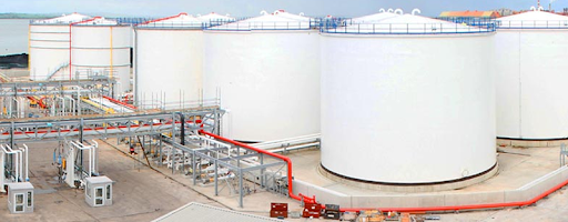
Tank Farm is an important part of any process plants as the storage tanks are required to feed in the several phases of processing or to store the finished product prior to its delivery to the customer.
Petroleum industries are one of the major users of the storage tanks. The storage tanks are usually placed within a common area (offsite) of the plant and it’s known as a tank farm. In most of the plants, offsite covers 70-80% of the total plot area, and most area of the offsite is captured by the tank farm.
In this article, we will learn the tank farm design considerations, storage tanks arrangement, tank farm length, and width calculation, and dyke wall height calculation.
Table of Contents
Types of Storage Tank
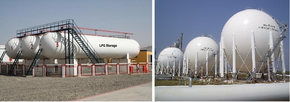
Storage tanks come in various shapes and sizes as per the requirement of the project. Spherical tank and bullet tank or horizontal pressure vessel are used for storing liquified petroleum gases (LPG) or pressurized fluid-like butane, methane(-280°F), propane(-43.7°F), etc. They are also known as high-pressure storage tanks or low-temperature storage tanks.
The larger tanks, it can be either a conical, elliptical, flat, open, or a floating roof, are usually used for storing liquid products. They are also called low-pressure storage tanks. Floating roof tanks automatically go up or down with the liquid level inside the tank and it helps to lower the evaporation and counter the build-up of dangerous gases that often occur with ignitable liquids.
Therefore, a good arrangement of the storage tanks is required to save the land and cost of the project. On another hand, good nozzle orientation and error-free piping layout are carried out for the smooth operation.
Inputs Required for Tank Farm Design
The Following are the major inputs required for tank farm design:
- Statutory and Safety Requirements
- Local Codes & Regulations
- Client Special Requirements
- Storage Tanks Specifications
- Storage Products Property and specifications
- Material of Construction
- The topography of the Plant Location
- Plant Layout
- Nearby Commercial and residential property details
- Adjacent Unit details
- Seismic data
- Maintenance & Operation Requirements
Related Codes and Standards
The following are the key codes and standards requirements in India for tank farm design. Although, these can vary based on geographical changes and local statutory requirements:
- OISD-118 (Layouts for Oil and Gas Installations)
- OISD-116 or 117 (For Fire Fighting requirements)
- NFPA (National Fire Protection Act), NFPA11, 30, 58, 59A & 321
- OSHA (Occupational Safety and Health Act)
- Petroleum Act of 1934
- API Standard 2610: Design, construction, operation, maintenance & inspection of Tank facilities
- SMPV-1981 (Static and Mobile Pressure Vessel)
- Local Safety Guidance.
- Factory Act of the State, if applicable.
- Fire Hydrant and Spray Manual Instructions.
- Insurance Requirements.
- Click here to see some important piping codes and standards and their applications.
Classification of Petroleum Products
Storage Product’s classification plays an important role in tank farm designing as the storage tanks are grouped or kept separated based on this classification. The storage products are classified based upon their flammability (Flash Point). Find the classification below:
- Class-A: Liquids which have flash-point is below 23°C
- Class-B: Liquids which have flash-point is 23°C and above but below 65°C
- Class-C: Liquid which have flash-point is 65°C and above but below 93°C
- Excluded Petroleum Class: Liquids which have flash-point is 93°C and above.
Important Note: Liquid Petroleum Gas (LPG) does not fall under these classifications. They come under a different category.
Installation Types
We must know the installation types of the tank farm, as based on these installation types, the designer needs to check the different tables in OISD-118 for storage tank arrangements and calculations. These are of two types:
- Small Installations: Aggregate capacity of the class-A and Class-B petroleum product storage tanks group is less than 5000 m3 or the diameter of the largest tank of the group is not exceeding 9 m.
- Large Installations: Aggregate capacity of class-A and Class-B petroleum product storage tanks group is greater than 5000 m3 or the diameter of the largest tank of the group exceeds 9 m.
Tank Farm Design Considerations
The below points are needed to consider while preparing the storage tank layout as per OISD-118.
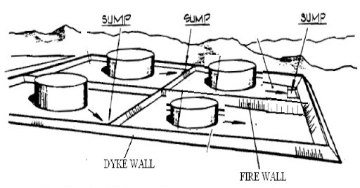
Dyke Enclosures
There is a risk of failure of the storage tanks or the piping system connected to it. Therefore, dyke or dike enclosures are designed to contain spills.
- Petroleum storage tanks should be located in dyke enclosure with roads all around.
- Pump station and piping manifold shall not be installed within dyke enclosure. They can be installed outside the dyke area by the side of the road.
- The aggregate capacity of the tanks placed in one dyke enclosure shall not exceed 60000 m3 for a group of fixed roof tanks and 120000 m3 for a group of floating roof tanks.
- If a group of tanks contains both fixed and floating roof tanks, then need to treat as the fixed-roof tanks only to not exceeds the limits of 60000 m3 for safety.
- Fixed cum floating roof tanks shall be considered as fixed roof tanks. Though, if the fixed cum floating roof tanks are equipped with windows opening on the shell and these windows will not get blocked at any cost, then these may be treated as floating roof tanks.
- The dyked enclosure should be able to accommodate the complete contents or product of the largest tank in the dyke in case of any failure in the tank or the piping system connected to it.
- The dyke enclosure capacity is calculated after deducting the volume of all the tanks (other than the largest tank) and the tank pads, foundations, and the stairs present within the dyke up to the height of the dyke wall.
- While calculating the dyke wall height, a freeboard of 200 mm is added to the calculated liquid level or dyke wall height.
- The dyke or dike wall height (including the freeboard of 200 mm) shall be a minimum of 1 m and a maximum of 2 m from the inside finish grade level.
- The dyke encloser or the dike wall can be made up of earth, concrete, or solid masonry, but it should be able to withstand the hydrostatic load.
- Earthern dyke wall width (flat section on top, not the inclined one) shall not be less than 0.6 m to ensure the stability of the dyke wall.
- For the excluded petroleum product storage tank, the capacity of dyke encloser should be based on spill containment only and not for containment of tank rupture.
- In the case of excluded petroleum, the minimum height of dyke wall shall be 0.6 m.
- The separation distance between the two nearest tanks located in separate dyke encloser shall not be less than the diameter of the larger of the two tanks or 30 m, whichever is more is considered.
Grouping of the Storage Tanks
- Grouping of the petroleum product storage tank shall be based on the product classification.
- Class-A and Class-B petroleum products can be stored in the same dyke enclosure. Whereas, Class-C petroleum products should be preferred to store in a separate enclosure.
- But, if for any reason Class-C petroleum product is being stored with Class-A & Class-B product in the same dyke enclosure, then all the safety rules shall be applied as per the Class-A or Class-B product.
- Excluded petroleum products should be stored in a separate dyke enclosure & it should not be stored along with Class-A, Class-B, or Class-C petroleum products.
- The Storage tanks should be arranged or installed in a maximum of two rows so that, each tank is attainable from the road surrounding the enclosure in case of any emergency. This condition needs not to be applied to the storage tanks containing excluded petroleum products.
- Tanks having a capacity of 50000 m3 and above shall be kept in a single row only.
Fire walls
- If more than one tank is installed in a dyke enclosure, then firewalls of a minimum height of 0.6 m should be provided to contain the spills from one tank hazarding to another tank in the same enclosure.
- There is no need to provide the firewalls to separate all tanks from each other if they are small installations (It means, a group of small tanks not exceeding the aggregate capacity of 5000 m3 or the diameter of any tank from the group not exceeding 9 m) then they are treated as one tank for the provision of the firewall.
- For excluded petroleum product storage tanks, the firewall height shall not be less than 0.3 m by limiting the number of tanks to 10 or the aggregate capacity of a group of tanks to 5,000 m3. Whichever is lower is considered.
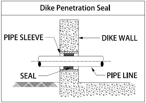
Sealing of Pipe Passing Through Dyke Wall or Firewall
The pump station is located outside the dike enclosure, Hence the pipeline connecting to the tanks from the pumps or other sources penetrate the dike walls. Therefore it is required to secure the leakage by using commonly available seals.
If the pipe is routed through an earthen dike or a firewall, the pipe shall be coated and wrapped. If the dyke wall or firewall is of concrete, the pipe should be sleeved.
General Considerations
- The tank height shall not preferably exceed 1.5 times the diameter of the tank or 20 meters whichever is less.
- The Piping from or to the tank should not pass from one dyke enclosure to another.
- Piping connected to tanks should route directly to the outside of the dike enclosure as much as possible to minimize piping within the dyke enclosure.
- The minimum distance between the tank outer shell and the inside surface of the dyke wall shall not be less than 0.5 times the tank’s height.
- There shall be linked roads to access on all four sides of each dyke enclosure to minimize the effect if one of the roads is cut-off during the fire emergency.
Separation Distances Between the Tanks For Above Ground Facilities Storing Petroleum Product
- For large Installation, minimum separation distances are specified in Table-3 and Table-4 of OISD-118.
- For small Installation, minimum separation distances are specified in Table-5 and Table-4 of OISD-118.
- Table-5 of OISD-118 is also applicable for Class-C Petroleum product storage tanks.
- Excluded petroleum product storage tanks shall be treated as a Class-C petroleum product for the purpose of separation distances and hence Table-5 is applicable for excluded petroleum products.
By keeping in mind the all above considerations, we are required to arrange the tanks in manners inside the dyke enclosure and then we need to calculate the tank farm length, width, and height of the dyke wall.
Don’t worry, I have a case study for you, please click here to check it out.
Separation Distances for LPG Storage Vessels
The minimum separation distances for above ground LPG storage vessels are specified in Table-6 and Table-7 of OISD-118. For mounded LPG storage vessel refer OISD-150.
The layout of LPG Storage Vessels
The considerations listed below are applicable to above-ground LPG storage vessels. For mounded LPG storage vessels, refer to OISD-STD-150.
- The pressure vessels should be arranged into groups each having a maximum of six vessels.
- The aggregate capacity of each group shall not exceed 15000 m3. If exceeding, then increase the number of groups.
- Each group of LPG storage vessels shall be equipped with a curb wall.
- The curb wall around the LPG storage vessels shall have a minimum height of 30 centimeters. However, it should not exceeds 60 centimeters cm at the shallow sump position, as evaporation of spilled LPG may get affected.
- The minimum distance between the vessels of the two groups shall be 30 meters.
- The spheres and bullets should not be located in the same group and minimum distances between the spheres and bullets groups shall be maintained by 30 meters.
- Longitudinal axes of horizontal pressure vessels or Bullets should not point towards other pressure vessels, tanks, vital process equipment, and control room.
- For the above-ground, 15 meters of the gap between the bullet’s longitudinal ends and other obstacles should be maintained to avoid any damages during the bursting.
- For underground bullets, the minimum gap is maintained by 6 meters.
- Pressure vessels should be located downwind of process units to avoid damages.
- Liquid petroleum storage vessels should not be installed within the same dyke enclosure where other liquid hydrocarbons are stored.
- The pressure vessels should be installed in a single row. In the case of both spheres and bullets.
- LPG vessels shall not be located one above the other.
- The spillage collection shallow sump should be located at a distance from where the flames from the sump fire will not affect the vessel.
- This distance should not be less than the diameter of the nearest pressure vessel or 15 m, whichever is higher is considered.
- The capacity of the collection sump should be in accordance with OISD-144.
To learn how to apply these Tank farm design consideration, Please click here
References
OISD-Standards-118, Revision-ii, September 2004
Loss Prevention in Process Industries by Frank P Lees
Process Piping Layout and Piping Design By Roger Hunt
You may also like to read
A Presentation on Pipe Stress Analysis
Reinforcement Pad Calculation for Branch Connection
Miter Elbow or Miter Bend Design Calculations
PDMS Commands: Piping, Equip, Structure & Draft
Some Important Piping Codes and Standards


I need answer for below question
how we connect 300# nozzle with 150# pipe flange ?
any technical solutions available please share with me.
Hello Sushil,
It is not recommended to connect different rating flanges together, however, if it is a compulsion then you need to match the no. of holes and PCD of both flanges, or the best option is to use Double Studded Adaptor for smooth connection.
For Crude Tank of 60 metre dia and 22 metre of height, how many spiral stair case is required from safety point of view. For 80 m, dia and 22 m height how many spiral stair case is required from design safety point of view, \
Is there any standard API, NFPA on the stair case how many required, or on top of tank we can connect inter connectivity of tanks on top Platform, near IFR – platform. So that more safety and people can escape through tank inter connectivity, and using another tank spiral stair case. Please write some details in this regards; Is there any Thumb rule for total number of Stair Case required for 60 m, dia or 80 m dia or 100 m dia tanks? please give me some clear idea?
Or is there any standard, on top side tank inter connectivity, at wind girder side, top platform so that in case of escape one person can use other stair case of another tank??
I need assistance on LPG Tank Farm design and loading pipes from ship. Thanks
Excellent piece Ahmed!
We seek to construct a Tank Farm for crude and for finished petroleum products. Would you know ant firm that would like to design and construct the tank farm in the Carebeans?
Keep up the good job. Thank you
Respectfully,
Victor A.N
Hollister California
YOU CAN SEND EMAIL TO [email protected]
YOU CAN SEND EMAIL TO [email protected]
Piping from / to any tank located in a dyked enclosure should not pass through any other dyked enclosure.
If passed what is your recommendation and what safegaurd shall be considered.
I am in need of assistance of a tank farm design in the USA. Do you know of anyone that you can refer me to?
Your design meet my design requirement for a tank Farm. It is modest but intensive.
I read your posted design. I like it. Can you please give more information as to the EPC construction of the design.
Can you please give more information
Thank you
Hi, How we can connect 300# pipe flange to 150# valve flange
That is possible with a flange connector.
Dear Sir Thank you so much for good explanation about Farm tank spec. My need is based Tanker construction spec. for 100 tone Edible oil. Basement, required size & length.