A pressure-temperature rating table or PT rating table is prepared to show the maximum allowable working pressure (MAWP) of the piping system at a different temperature range.
PT rating table can be found in the piping material specification(PMS) document. In this article, we will learn, how to prepare a pressure-temperature rating table for a complete piping system.
Table of Contents
What do you mean by Pressure-Temperature Rating?
A Pressure-temperature rating of the piping systems is defined as the maximum pressure withstanding capacity of the piping system throughout the design temperature range. As the temperature increases in the system, the pressure holding capacity decreases.

How does the PT Rating Table Look Like?
We can find the Pressure-temperature rating table in the piping material specification (PMS). It shows the maximum pressure withstanding capacity of the piping system at a different range of temperatures. PT rating table is attached below.

The pressure-temperature rating calculation for the piping system is done by the two methods-
- Full Rating Basis
- Line Basis or P/S Ratio Method
Full Rating Basis
In the full rating basis method, the flange is made weakest or the pipe is made stronger. It means flange will always be considered weaker in the piping system.
The minimum pipe wall thickness shall ensure that the flange becomes the weakest commodity. This method is based on the exact design condition provided by the process department.
Line Basis or P/S Ratio Method
The line basis method is also known as the P/S ratio method. Unlike the full rating basis, it is not necessary that the flange is made weakest or pipe is made stronger.
Pipe wall thickness is decided based upon the new design pressure & temperature achieved from the maximum value of the P/S (pressure/allowable stress) ratio, and whatever thickness is arrived is taken as the final thickness. The pressure withstanding capacity of this final pipe thickness is dedicated to the piping system if it less than the flange pressure withstanding capacity.
But, if the pipe pressure withstanding capacity is more than flange pressure withstanding capacity, then the flange pressure withstanding capacity will be declared for the piping system.
In the line basis, the declared pressure withstanding capacity may come from pipe or flange. But, on a full rating basis declared pressure withstanding capacity will come from flange only.
Okay!
Still, Confuse..?
Let’s do a case study to understand the difference between both methods and to learn how to prepare the PT rating table out of it. But, you need a little patience, as this article may be slightly longer.
Before moving to the case study, we must know which method should be used for pressure-temperature rating calculation.
Which method should be used when?
Which method is needed to apply for the calculation depends upon the below conditions:
- For Piping Class up to 300# Flange, full rating basis is used
- For Piping Class above 600# Flange, line basis is used
- For Piping Class 600# Flange, both methods can be used
Now, let’s move to the case study, we will do the calculation for class 600# so that we can apply both methods to understand the difference.
Inputs Required
The required inputs are as Follows:
Line Size- 1/2″ to 24″
Line Type- Up to 14″ seamless and above 14″ welded
Pipe Material (MOC)- Up to 14″ A106Gr.B and above 14″ A672Gr.B60
Design Pressure- 800 PSI
Design Temperature- 420°C
Mill Tolerance- 12.5% for seamless pipe and ±0.3mm for welded pipe
Corrosion Allowance- 3 mm
Flange Rating or Class- 600#
Flange Material- A105
Note: The flange rating is decided based on the design temperature and pressure of the piping system. Click here to see, how to decide the flange rating or class?
Calculation Steps on the Full Rating Basis
Follow the below steps for the calculation:
Step 1: Calculate the pipe wall thicknesses for all the pipe sizes as per the given design pressure and temperature by the process department.
We have already discussed the pipe thickness calculation in the other article. If you don’t know, how to calculate pipe wall thickness, click here to learn (it is very easy).
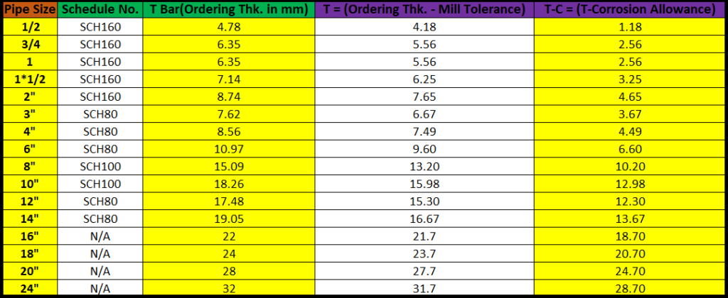
I have calculated the pipe wall thickness for our case below (Fig. 3)-
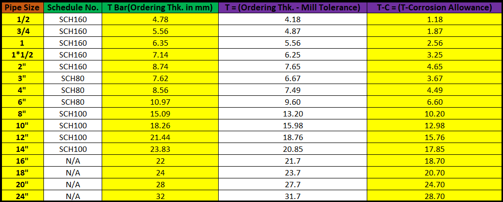
We were required to calculate the pipe ordering thicknesses only, but the value of T-C will be required in further calculation steps. T-C is nothing but the value after deducting mill tolerance and corrosion allowance from the ordering thickness.
Note1: I have not calculated the pipe thicknesses for 1*1/4″, 2*1/2″, 3*1/2″, 5″ and 22″, as these pipe sizes are not commonly used in the industry.
For your ease, you can do these calculations in the excel sheet.
Step 2: Find the pipe material allowable stresses at a different temperature range
We need to find allowable stresses for different temperature ranges, but this temperature range should not exceed the design temperature. For our case, we will not go beyond 420°C.
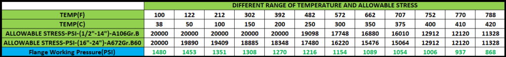
Let’s find allowable stress at 38°C, 50°C, 100°C, 150°C, 200°C, 250°C, 300°C, 350°C, 375°C, 400°C, 410°C, and 420°C
Note: This temperature range is not fixed, you can take any temperature ranges within the design temperature.
See the below figure (fig. 4) to find out the allowable stress value for pipe A106Gr.B at temp. 38°C or 100°F, we can find the value of allowable stress from Table A-1 of ASME B31.3.
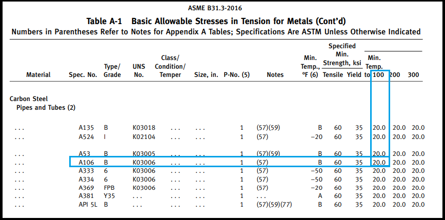
From the above figure, we can see allowable stress for A106Gr.B at 38°C or 100°F is 20 Ksi or 20000 Psi.
Similarly, we need to find allowable stress for A106Gr.B & A672Gr.B60 at all the temperature ranges. I have prepared the table below after finding out all the values.

Step 3: Find the working pressure of flange for all the temperature range
we can find these working pressure from the PT rating table mentioned in the ASME B16.5.
The pressure-temperature rating table number can be found from Table 1A of ASME B16.5 based on the flange material, and then the working pressure can be found from respective PT rating table.
Let’s find the working pressure of class 300# flange (MOC-A105) at 38°C.
First, we need to find PT rating table number as per the flange material.
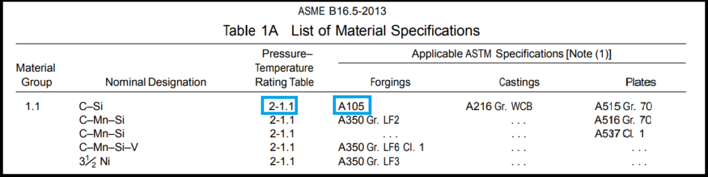
From the above figure, we can see that for Flange A105, pressure-temperature rating table number is given 2-1.1
Now, go to the table 2-1.1 of ASME 16.5 to check the working pressure.
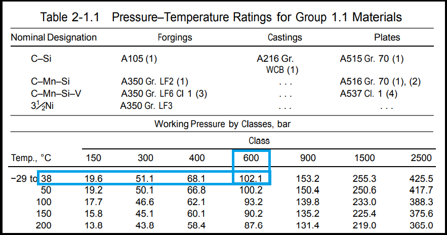
From the above figure, we can see that, for class 600 flange, the working pressure is given 102.1 Bar = 1480 Psi at 38°C.
Similarly, we need to find working pressure for all the temperature ranges. I have listed below the flange working pressure (Fig. 8)
Step 4: Calculate the maximum allowable working pressure (MAWP) for pipes using the below equation
As per ASME B31.3, the below equation is used to calculate the maximum allowable pressure for pipe
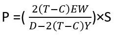
Where,
P= Maximum allowable working pressure (MAWP)
T-C= Ordering thickness – (mill tolerance+corrosion allowance)
E= Quality factor for longitudinal weld joints in the pipe
W= Weld Joint Strength Reduction Factor
Y= Values of Coefficient
S= Allowable stress
The value for T-C, E, W & Y, you will get while calculating the pipe wall thickness, and the value for allowable stress (S) will be taken from figure fig. 5, as we have already found the allowable stress for pipe material.
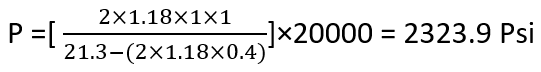
So, let’s start the calculation for MAWP, we are going to first calculate for 1/2″ NPS (A106Gr.B) at 38°C. Put the required values in the above equation.
MAWP for 1/2″ NPS at 38°C
Similary, MAWP for 3/4″ at 38°C
P= 2959.4 Psi
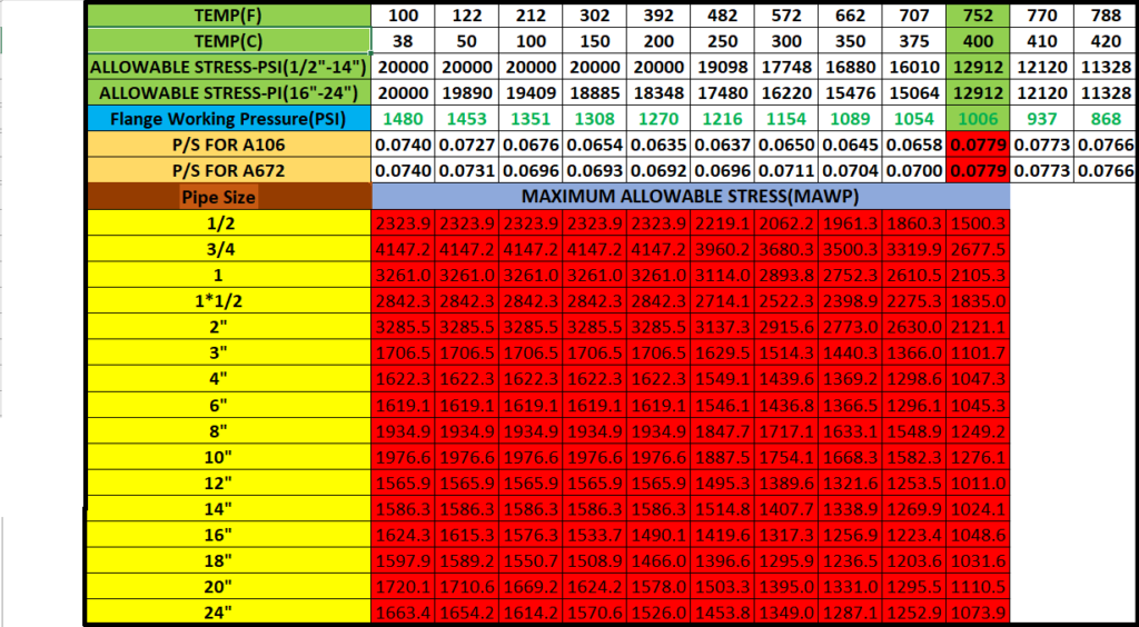
Likewise, we have to calculate the MAWP for all pipe sizes at all the temperature ranges. I have calculated these values, check it out in the below figure.
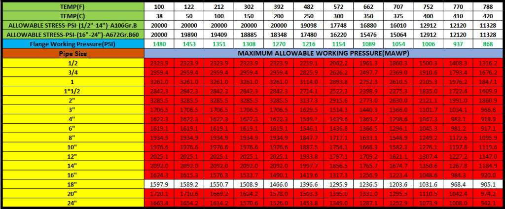
Now, from the above-calculated value table, we need to find out the minimum value of MAWP for pipes in each column. If that minimum value of MAWP is less than the working pressure of the flange of that same column, then we need to increase the thickness of that particular pipe, and again need to calculate the MAWP of the pipe based on the new pipe thickness. As the definition says for the full rating basis that flange is always made weakest. So, for making the pipe stronger we will have to increase the pipe thickness.
The above process shall be repeated until the minimum MAWP of the pipe becomes greater than flange working pressure. If once, we got the minimum MAWP of the pipe is greater than the flange working pressure of that line then that particular MAWP will be declared for the PT rating table at that temperature range.
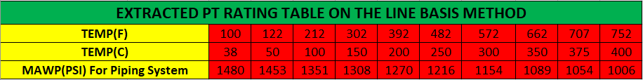
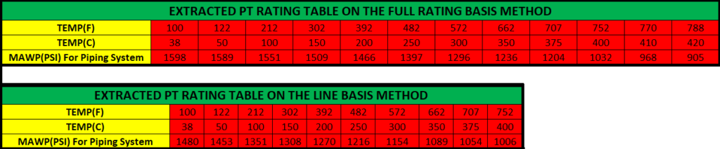
The same process will be repeated for all the columns. Let’s see below the extracted final PT rating table after following all steps above.

Now, let’s solve the same problem with the Line Basis method to see the difference between both methods.
Calculation Steps on the Line Basis or P/S Ratio Method
Follow the below steps for calculation:
Step 1: Calculate the P/S ratio
Where,
P = Working pressure of flange
S = Allowable stress for pipe material
In the full rating basis method, we have calculated these values. Now, we will have to only divide these two values. I have done these calculations, see the figure below.
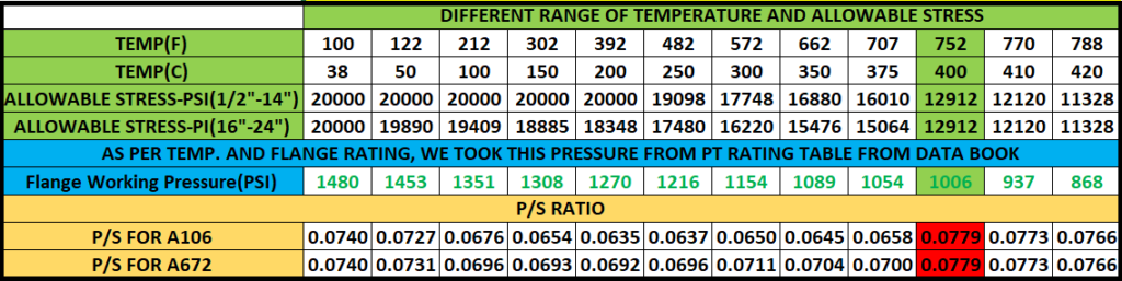
From the above figure, we need to find out that at what temperature the P/S ratio is maximum. For our case, we can clearly see that at 400°C the P/S ratio (0.0779) is maximum.
Therefore, this temperature (400°C) and pressure (1006 Psi) combination will become the new design pressure and temperature for this piping system. On the full rating basis, we used the design pressure and temperature that was provided by the process department, whereas in the line basis method, the design pressure and temperature provided by the process department may change to the new design pressure and temperature.
Step 2: Now, calculate the pipe wall thickness based on the new design temperature and pressure
I have calculated below the pipe wall thickness based on new design pressure and temperature.
Step 3: Now Calculate the MAWP of the pipe
As, we calculated the MAWP of pipe for Full Rating Basis, in the same manner, we need to calculate for Line Basis as well. I have calculated the same below.
Now, from the above figure, find out the minimum value of the MAWP for the pipe in each column, and then compare this minimum value by working pressure of the flange of that same column, Whichever is less that value will be finalized for that temperature range. There is no need to change the pipe thickness in this method. Because, the definition says for line basis, the weaker one (Pipe or Flange) will be considered.
I have extracted the PT rating table from the above figure.
Comparison Between Both Methods
We will see some parameters below to compare the end results of the both methods:
Pipe Thickness Comparison
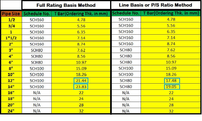
We can see in the above figure, for 12″ and 14″, pipe thicknesses in both methods is not matching. It means, in the full rating basis method, pipe thickness has been increased to make flange weakest.
Pressure Temperature Rating Table Comparison
These calculations required practice, So please do practice to understand it better. If still any query, feel free to comment below, i will try to revert you back as soon as possible.
You may also like to read
A Presentation on Heat Exchanger
Some Important Piping Codes and Standards
Miter Elbow or Miter Bend Design Calculations
Reinforcement Pad Calculation for Branch Connection
Pipe Rack Design and Calculations

You have not mentioned interpolation between intermediate temperatures. This can avoid stepping up a piping class, which is very costly.
Also process design conditions, are generally not accurate. They are based on operating conditions + design/safety factors, subjective opinions by the originator, rounding up. This results in excessive desisn pressure and temperatures and this will distort the results when calculating flange ratings.
Hi Peter,
I have mentioned about the interpolation between intermediate temperatures in another post, link has been added to this post.
Allowable stress for A106-B at temp 250 celcius is 132 mpa as per asme viii div1 but you mentioned in your table at 250 degree , 19098psi
This allowable stress value is as per ASME B31.3, and still, you can see there is no major difference as per both standards.
I am a serious young graduate, looking for a beginner job as a metallurgical engineer or Pipeline Technology Engineer.
My goal is to develop my skills in your business, and offer all my life.
+213676729103
Hi
How to obtain 12120 psi at temp 770 F ?
Could you show formula and say its standard plz?
The value 12120 psi is as per Table A-1 of ASME B31.3.
Interpolation is used for the middle range of value.
you’re right ,in edition 2008 but in 2014 and above has changed minor
Hi Sir
Why MAWP for 3/4″ Od in at 50 celcius become 4147??? In first table 2959 😯 why increase thk???
Hi.
In the full rating basis example, why do you prepare the PT rating table based on the MAWP of the pipe?
As you say at the beginning of your article, for the full rating basis method, the flange is always the weakest component, and the declared pressure withstanding capacity should always come from the flanges.
Your exact words: “In the line basis, the declared pressure withstanding capacity may come from pipe or flange. But, on a full rating basis declared pressure withstanding capacity will come from flange only.”
Thank you for your time and this valuable information.