Moving fluids play an important role in the process of a plant. The liquid, gas, or slurry fluid can only move by its own power, if only it flows from top to bottom or from high pressure to a lower pressure system. But, when it is the requirement of the system to move the fluid from bottom to top or from lower pressure to higher pressure system then it requires an external force to make this happen. This external energy exerted on the fluid is generated by the pumps. This article is going to give you an overview of the pumps used in the oil and energy industry mainly focused on the centrifugal pump and the positive displacement pump.
Table of Contents
Introduction to Pump
A pump is a mechanical device or machine which is used to transfer the quantities of fluids or gases from one place to another place. In other words, we can say that pump converts the mechanical energy of the motor into the fluid flow energy.
The pumps also can be used in a system that requires high hydraulic pressure. You can see this application in the heavy-duty equipment. Often the heavy-duty equipment is needed high discharge pressure and low suction pressure. Because of low pressure at the suction side of the pump, fluid lifts from a certain depth, whereas because of high pressure at the discharge side of the pump, it pushes the fluid to lift, until it reaches the desired height.
Types of Pumps
The pumps can be classified on the basis of the applications, construction type, material of construction, type of liquid they handle, and their orientation in the space.
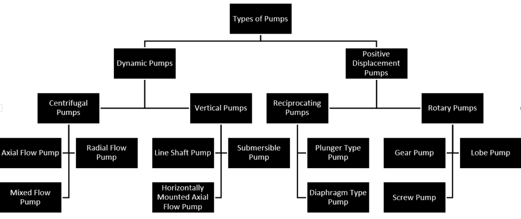
All such classifications are limited in scope and can overlap each other. To make the classification easy, it can be classified based on the principle by which energy is applied to the fluid. Under this classification method, all the pumps generally fall into two main categories –
- Dynamic Pumps – Energy is continuously applied to increase the fluid velocities within the system.
- Positive Displacement Pumps – Energy is periodically applied unlike the dynamic pumps
These are further divided into many types as per their construction and working:
We will go further in details with the most commonly used pumps in our industry:
- Centrifugal Pump
- Positive Displacement Pump
Centrifugal Pump
Centrifugal pumps are the most popular and most commonly used pumps, which are used for transferring the fluid. An impeller is used in the centrifugal pumps which have curved blades that accelerate fluids towards their edge when it rotates. The impeller is normally powered by an electric motor, and its movement produces suction (pressure dropped or vacuum) at the pump inlet, which results in drawing water inside the housing and discharge it out with higher energy.
Generally, centrifugal pumps are designed for liquids that have a comparatively low viscosity like light oil and water. If still, it is used with the high viscous fluids then it will require extra horsepower to run the centrifugal pumps efficiently. Centrifugal pumps mainly include three parts such as an impeller, a casing, and a suction pipe followed by a foot valve and a strainer.
Centrifugal pumps benefit due to its simple design with few moving parts, which results in lower maintenance requirements and overall costs.
Based on the flow type, centrifugal pumps are classified into three sub-types. The different flow pattern is achieved by both the impeller shape and pump construction.
- Axial Flow Type
- Radial Flow Type
- Mixed Flow Type
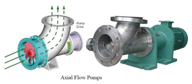
Axial Flow Centrifugal Pump
It produces flow parallel to the shaft axis with a lower head and very high discharge rate. The axial flow type pump is used, where the lower head and high discharge is required.
In this type of centrifugal pump, the pressure is developed by the lifting action of the vanes or blades of the impeller on the liquid. The ratio of impeller outside diameter to eye diameter is one and the impeller having no width.
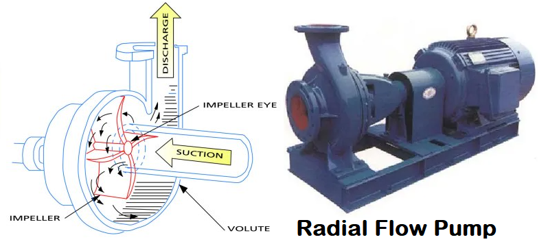
Radial Flow Centrifugal Pump
It produces flow perpendicular (90°) to the shaft axis with a higher head and low discharge rate unlike the axial flow type centrifugal pump. It means the impeller discharges the fluid perpendicular to the shaft. The radial flow type pump is used, where the higher head and low discharge is required.
In this type of centrifugal pump, the pressure is developed by centrifugal force. The ratio of impeller outside diameter to eye diameter is two and the impeller having a narrow width.
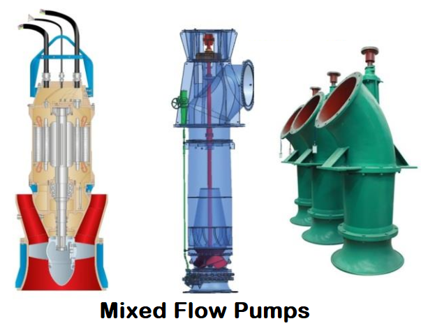
Mixed Flow Centrifugal Pump
As the name suggests, it produces flow partially axial and partially radial which further gets converts the conical flow pattern around the impeller shaft axis. The mixed flow types centrifugal pump is used, where the medium head and medium discharge is required.
In these types of centrifugal pumps, the pressure is developed partially by centrifugal force and partially by the lifting action of vanes of the impeller on the liquid. The ratio of impeller outside diameter to eye diameter is less than 1.5 and the impeller having wider width.
Priming of Centrifugal Pump
The priming of the pump is the most important step before starting a centrifugal pump. Because these pumps are not capable of pumping out the vapors, air, or gases contained in the passageways of the pump. So, pump-priming is required to push out these things from the passageways of the pump.
The priming methods are mainly classified into four types:
- Manually
- By vacuum pump
- With a jet pump
- With a separator
Advantages of Centrifugal Pump
- Drive seals do not exist in centrifugal pumps, which reduces the leakage risk. This means that toxic fluids can be pumped without any spillage.
- These pumps can be used to pump out the toxic fluids.
- It includes the magnetic coupling that can be failed easily in overload situations. It also as protects the pump from external forces.
- These pumps are constructed in a manner that the motor and pump are separated from each other, which prevents the heat transfer from the motor to the pump.
- Low friction generation
- The process fluid can not seep into the motor due to the proper gap provided between the pump casing and the motor.
Limitations of Centrifugal Pump
- The energy loss can be occurred due to magnetic coupling. This is because the particles get collected on the impeller magnet, and after some time, it can cause to stop the pump working.
- If the pump is under unexpectedly heavy loads, it may cause the coupling to slip.
- If the fluids with ferrous particles are swiped out, it can cause the occurrence of rust, and over the time pump stops working.
- When the fluid flow is less throughout the pump, then the overheating can occur.
- Not suitable for a highly viscous fluid.
- Centrifugal pumps are not inefficient for low flow and higher head application, as it requires a large body to deliver such configuration.
Applications of Centrifugal Pump
These pumps are broadly used in the following applications:
- In the oil and energy industries for pumping oil, water, mud, and slurry.
- For Power generation plants
- These pumps are broadly used in chemical, processing, petrochemical, and hydrocarbon industries.
- In the Fire fighting system, boiler feed, and air conditioning system
- Used in the waste management system and agriculture
- At water treatment plants
A Short Video on Centrifugal Pump
How to find out the efficiency of Pump
The efficiency of a pump can be defined as the ratio of the water power (output) to the shaft power (input). The pump efficiency can be calculated using the below equation (1):
Ef = PW / PS
Where,
Ef = Pump Efficiency
PW = Water Power
PS = Shaft Power
The water power (PW) can be found using the below equation (2):
Pw = (Q x H) / 3960
Where,
Q = Flow rate
H = Head
3960 = Constant (it changes the flow rate and head into BHP (Brake Horsepower)Gallons Per Minute
Let’s solve an example: What is the efficiency of a pump, if a pump generates 120 GPM (Gallons Per Minute) on 35 feet of head, and shaft power is 1.5 BHP?
We have from the problem,
Q = 120 GPM
H = 35 feet
PS = 1.5 BHP
Put the required inputs in equation (2)
Pw = (120 x 35) / 3960 = 1.06 BHP
Now put the required input in equation (1)
Ef = 1.06 / 1.5 = 70.7 % (This is the calculated efficiency of the pump).
we can also calculate the pump capacity by the reverse calculation using the same equation.
Some Typical Problems that may occur in the Pump
- Cavitation: It can occur when the net positive suction head (NPSH) of the system is too low for the selected pump. In other words, the vapor pressure inside the suction line should be less than the atmospheric pressure but not less than the vapor pressure of the fluid to avoid cavitation.
- Wear of the impeller: Excessive wear can occur in the impeller due to the pitting effect, and this condition can often be worst if the solid particles are not removed from the suction line.
- Corrosion: Due to the corrosive nature of the fluid, the pump can be corroded.
- Surge or back surge: Due to rapid change in the velocity of flowing fluid.
- Overheating of the pump: Due to the low flow rate overheating can occurs in the pump.
- Leakage: The leakage can exist around the rotating shaft.
- Lack of prime: Centrifugal pumps must be pre-filled with the fluid to be pumped.
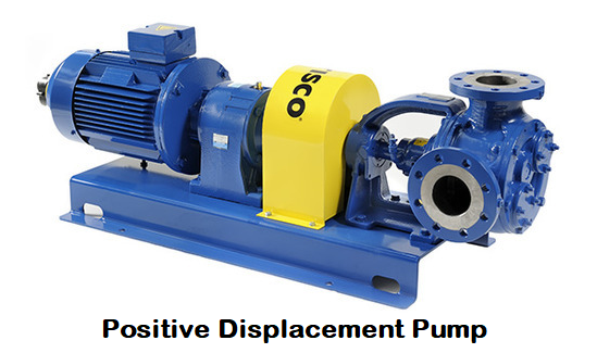
Positive Displacement Pump
Positive displacement pumps pumped out a fixed amount of fluid at regular intervals. They’re built with internal cavities that fill up at the suction side at regular intervals, and it gets discharged with higher pressure at the outlet. The action of the pumping from the inlet to the outlet of the pump is cyclic which can be achieved by screws, pistons, rollers, gears, diaphragms, or vanes.
The liquid in this pump can be captured inside a cavity to discharge the set amount of liquid. The liquid dislocation can take place with the help of few parts namely the piston, diaphragm, and plunger. The cavity at the suction side of the pump is in increasing form and the cavity is in reduced form at the discharge side of the pump. Because the liquid can be sucked at the inlet side when the cavity increases, and get discharge whenever the cavity reduces.
Based on how the liquid is displaced, positive displacement pumps can be categorized mainly in two types:
- Reciprocating Type
- Rotary Type
Reciprocating Type Positive Displacement Pump
The Flow is stabilized by a cavity that expands and contracts, like a piston movement. Water moves into the cavity while expansion and is pumped out during the contraction, while the flow direction is controlled with check valves, which prevent the backpressure or reverse movement of fluid.

Example: Bladder, Diaphragm, Peristaltic, Piston/plunger type pump
Rotary Type Positive Displacement Pump
This type of pump uses a rotor that traps water in the cavities and then releases it at the pump outlet. These cavities are the spaces between gear teeth or screw threads, among other rotor configurations
In some designs case, the numbers of the shaft can be used more than 1, but the principle is the same for both arrangements. The rotor shape is designed to create pockets of water and displace them in the intended direction.
Example: Gear, Screw, Progressing cavity, Rotary lobe, Rotary vane-type pump
Applications of Positive Displacement Pump
These pumps are broadly used in the following applications:
- Piston or Plunger pumps: Used for low viscous fluids like paint spraying, oil production, and washing purpose.
- Diaphragm pumps: Used for spraying and water treatment application.
- Gear pumps: Used for high viscosity fluids
- Lobe pumps: Used in food, chemical, pharmaceutical, biotechnology, sanitary, etc.
- Screw pumps: Used for fuel transferring, oil production, etc
- Vane pumps: Used for low viscosity liquids mainly for fuel loading and transmission.
These applications are not limited to this only, these pump can also be used at some other places
Why Positive Displacement Pumps are Preferred over Centrifugal Pump?
The reason for using positive displacement pumps are as follows:
- It can be used with a high viscous fluid.
- It works efficiently for low flow (discharge) and higher pressure (head) combination.
- Self-priming capability.
- Low cost due to compact size for low discharge and higher head combination.
- The flow rate or discharge rate remains constant with a change in pressure.
- It creates a vacuum at the inlet side of the pipe, which makes them capable of creating a suction lift.
- Due to low internal viscosity, little shear is applied to flowing fluid, therefore, ideal for shear sensitive fluids.
Pump Selection Criteria
The pumps are selected based on the following parameters:
- Product or Fluid Data: It includes viscosity, density, specific gravity, temperature, flow characteristics, vapor pressure, and solids content of the fluid.
- Performance Data: It includes capacity, flow rate, suction, and discharge pressure or head.
You may also like
Reinforcement Pad Calculation for Branch Connection
Miter Elbow or Miter Bend Design Calculations
Pipe Wall Thickness Calculation For External Pressure or Vacuum
A Presentation on Heat Exchanger


This is required for use in a oil refinery.
Excellent article on Centrifugal Pumps. Reading this gave me an idea of Centrifugal Pumps and their types. Thanks for sharing your information! Learn more about Types of Centrifugal Pumps in monarch blogs.
I like that you pointed out how centrifugal pumps can be used to pump out toxic fluids. I was looking into some industrial equipment earlier and I learned about the various available pumps nowadays. One of the most common types I saw was the ANSI centrifugal pump.