The pump piping design can have an important impact on the operating efficiency and life expectancy of any pump. Hence, the piping design engineer must consider the important points while designing the pump piping layout. The design of a suction and discharge line should be delivered keeping in mind the operability, maintainability, flexibility, and support requirements of the piping system.
Poorly designed pump suction piping can result in the entrapment of air or vapor into the pump piping and cause cavitation, which displaces liquid within the pump casing, which results in vibrations, and damages to the pump impeller. Here, we will learn the design consideration and different layout patterns for pump piping.
Table of Contents
Important Points to be Considered While Designing Pump Piping
- The suction pipe size should never be smaller than the pump suction nozzle. In most cases, it is one size larger than the suction nozzle.
- The suction line should be as short & straight as possible.
- The suction line should be pocket free.
- All the pump suction lines need to be designed to accommodate a conical-type temporary strainer for commissioning and testing.
- The suction and discharge line piping should be supported independently of the pump foundation.
- Expansion joints can be used on either the suction or discharge line side or both as per requirement. However, expansion joints are the last option and should be used only when it is unavoidable.
- If expansion joints are used then a pipe anchor must be given between the expansion joint and pump nozzle to prevent the pressure loads from getting transferred to the pump nozzle.
- The suction piping should preferably be horizontal and at a slope toward the pump suction nozzle from the sump.
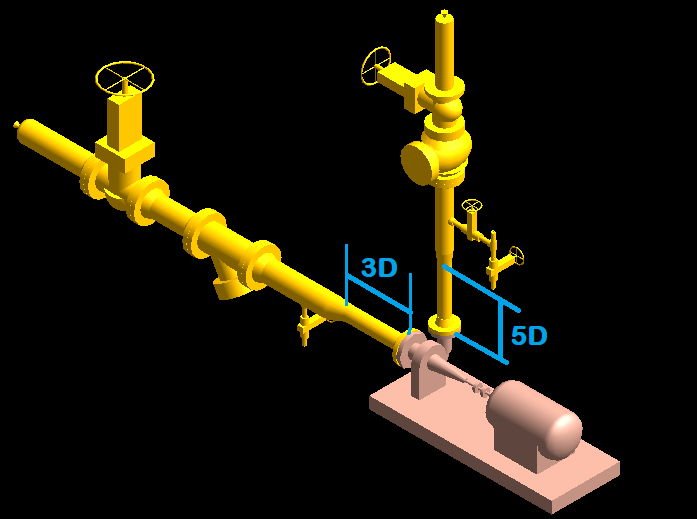
- When the suction piping is in a horizontal plane, we should provide a minimum of “three to five times the diameter of the suction nozzle” straight pipe length between the pump suction nozzle and the first elbow or a flange, valve, tee, or strainer. The reducer may be included in that straight length.
- The mating flange of the suction line with the pump suction nozzle should be of the same rating and material as the pump suction nozzle.
- The suction pipe velocity should be within 2 m/s, as higher velocities will cause friction loss.
- Elbows and tees should be avoided to install adjacent to the pump suction nozzle as it causes an uneven flow pattern inside the suction line.
- If an elbow is needed at the suction line of a double suction pump, it should be preferred to be in a vertical position. If it is important for some reason to use a horizontal elbow then it should be a long radius elbow.
- Pump piping should be designed with adequate space to facilitate the removal of the pump for maintenance purposes.
- Lifting facilities are provided where the weight of the component exceeds 25 kilograms. So it is required to provide space for mobile equipment to deliver damage-free maintenance.
- The Spare pump should be considered while designing the pump piping as a backup pump is required to deliver continuous production in case of the main pump maintenance period.
- The pump piping should have removable spool pieces with breakup flange if they obstruct the lifting operations.
Fittings and Components Used in the Pump Suction Line
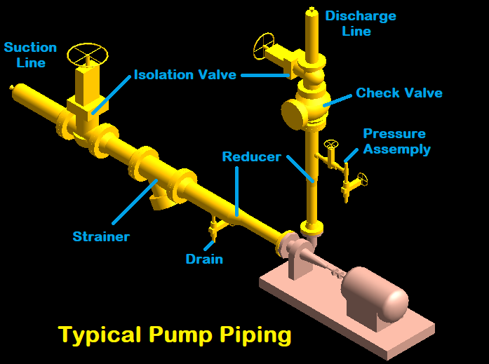
The most commonly used piping fittings and components in the suction line are as follows:
Isolation Valve
The isolation valve (mostly gate valve) must be provided on the suction line upstream side of the strainer to allow its removal during maintenance or to isolate the complete suction line. It should be located within three meters of the pump suction nozzle for efficient delivery and it should be convenient for hand operation. Usually, the size of the isolation valve is the same as the suction line.
Strainer
Strainers are used in the suction lines to collect the debris flowing with the fluid which prevents damaging the internal parts of the pump. Strainers are located between isolation valves and the reducer or pump nozzle. Temporary strainers are used at the initial stage after the pump has run successfully for several days the isolation valve can be closed and a temporary strainer is removed.
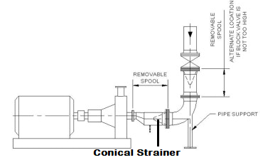
The temporary strainer is always of conical type and installed at the removable spool. The permanent strainers can be either Y-type, T-type, or bucket type. They are used as per the line size, fluid nature, and piping layout.
Drain
Low point drains are provided in the suction line (mostly between strainer and reducer). It is required during the hydro testing and maintenance of the line to drain out the fluid completely from the suction line.
Reducer
Due to the suction line being larger than the pump suction nozzles, reducers are required to maintain the differences in the line. Reducers should be installed as close as possible to the nozzle to avoid turbulence inside the line.
Eccentric reducers flat side up or flat side top are used in the horizontal suction line. Eccentric reducer (FSU) prevents vapor from being trapped and encouraging the phenomenon of cavitation which can further damage the pipe and pump impeller.
If the horizontal suction line carrying slurry inside then it is required to provide an eccentric reducer flat side down or flat side bottom type for smooth flow of slurry.
If the reducer is installed in the vertical line then it should be a concentric reducer unless there is a special requirement.
Fittings and Components Used in the Pump Discharge Line
The most commonly used piping fittings and components in the discharge line are as follows:
Reducer
In most of the cases, a concentric reducer is used in the discharge line and it is kept near to the discharge nozzle as much as possible. The straight pipe length between the discharge nozzle and reducer is required to keep a minimum of 5 times the diameter of the discharge nozzle. The reducer length may also be included in the straight length.
If the discharge line is in a horizontal plane as in the case of side suction side discharge pump then the eccentric reducer flat side down can be used for ease of the support.
Pressure Gauge Assembly
The pressure gauge should be located on the discharge line before the check and isolation valve to keep eye on discharge pressure. Pressure gauge assembly can have the drain as well.
Check Valve
Check valves are generally installed in the discharge line after the reducer and pressure gauge assembly to prevent backflow. A check valve is a one-way valve, in which the flow can run freely one way, but if the flow turns back then the valve gets close to prevent the line from backflow.
If the flow turns back and there is no check valve is installed, then the water hammer can occur. Sometimes water hammer occurs with an intense force and can easily damage piping components and the pump.
Up-to 1*1/2″ Lift Type Check Valve is used and it can be used in a horizontal and vertical line as well.
Above 1*1/2″ Swing Type Check Valve is used and it is mostly installed in a horizontal line. If required up to 6″ swing check valve can be installed in a vertical line but above 6″ check valve should be installed in a horizontal line only.
Isolation Valve
The isolation valve (mostly gate valve) is installed just after the check valve to isolate the discharge line and to remove the check valve for maintenance, as the check valve required regular maintenance. The isolation valve is installed by keeping in mind the operability due to its frequent usability.
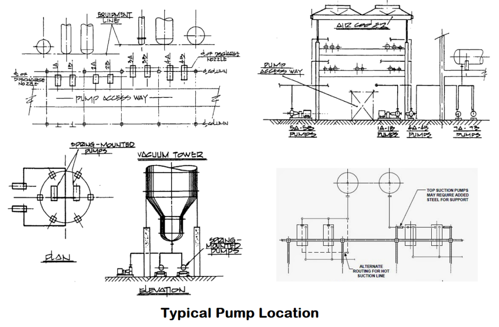
Pump Location
The pump location may vary for many reasons. The main goal in setting the location of the pump is to minimize the length of the suction piping while fulfilling the piping flexibility requirements and allowable loads that will be subjected to the pump nozzles. Let’s see below some point for pump location:
- The common location of pumps in the hydrocarbon industry is under the pipe rack at grade level. Click here to see the pipe rack design
- Pumps should be placed as close as possible to the vessel or sump and below the vessels in order to fulfill the net-positive suction head (NPSH) required by the pump.
- As per the OISD-118, the Pump should be kept outside of the Tank farm or dyke wall by maintaining the minimum distance as per the stored fluid class.
- As per OISD-118, the minimum gap between the two pumps should be 1 meter.
- Standard pipe rack column spacing is 6 meters, it is generally found that only a pair of pumps of average size can be arranged between the two-columns.
- As per engineering practices, the minimum gap between the steel structure and discharge piping should be 0.75 meters.
- The centerline elevation of the pump can be decided based upon the space required for the strainer maintenance, as per engineering practices the minimum gap between the suction line and grade level is taken 300 mm. This gap is not fixed it can vary from company to company.
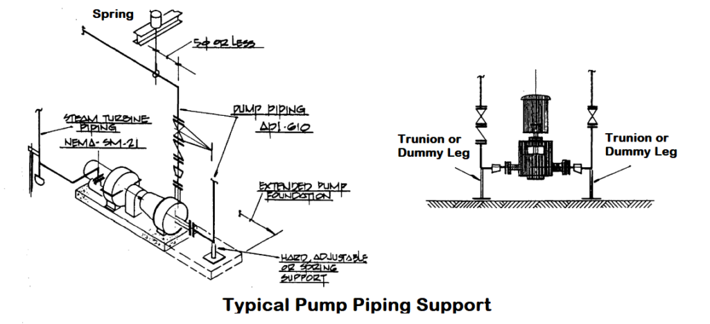
Pump Piping Support
A piping layout engineer must be aware of some basic knowledge of stress and pipe supports to develop a sound pump piping arrangement, so that it will not be required to redesign by a stress engineer after finding out the piping design is not stress friendly.
Some simple rules, if followed, it will enable the designer to deliver stress friendly pump piping:
- If the suction line having an elbow, it can be supported with a dummy leg or trunnion.
- The discharge line can be supported with the pipe rack steel structure or it can be supported by hanger or spring support as per the convenience.
- If there is a higher amount of vibration in the line then to release the stress expansion joint can be used, but it should be avoided.
- If the pumps are located in the poor soil areas, where differential settlement may occur, the pump foundation can be extended to support the suction line. This decision can be taken by keeping stress and civil engineer in the loop.
- The discharge line should be supported as close as possible to the elbow, the closeness can be defined as within 5D.
- If the line is having high pressure and temperature then adjustable support can be used to provide flexibility.
- If the valve is too heavy then both sides of the valve resting support can be provided.
- If the discharge line is larger than 6″ then after the reducer line can be kept horizontal so that there will ease to support and operating of both valves.
By keeping in mind the above design considerations, different piping arrangements or layouts can be created, some companies also use the standard pattern, and from time to time as per new challenges the design gets modified.
You can get your chemical dosing pump in Saudi Arabia from Ejawda
You may also like to read
Types of Pumps: Centrifugal Pump & Positive Displacement Pump
Reinforcement Pad Calculation for Branch Connection
Miter Elbow or Miter Bend Design Calculations
Pipe Wall Thickness Calculation For External Pressure or Vacuum
Some Important Piping Codes and Standards
Miter Bend Calculations For Fabrication Purpose
References
Piping Hand Book by Mohinder L. Nayyar, P.E.
Piping and Pipe Line Engineering By George A. Antaki
Process Piping Layout and Piping Design By Roger Hunt


Hi Mr. Rehan
How are you?
This is Rostam Yazdani from Iran. Your job and your thought is really appreciated. I believe this industry is really great. I have been working in this industry for a long time. But mostly I have been at site / project, such as; gas refinery, crude oil refinery, crude oil pump stations, power plant and oil terminal. I am also a mechanical engineer. And I have experience working in technical office, piping QC, fix & rotary equipment installation expert and QC of mentioned equipment, welding inspector and also welding RTI, construction executive in flare piping and etc. And very much dominant and familiar with the related standards and specifications. Well, I would like to say that recently I am working with an EPC contractor in the mechanical engineering department of a crude oil storage depot.
Frankly, I am very much interested in piping stress analysis and the manual piping calculations. It would be so kind of you if you could help me out through. As long as you are a professional piping expert, I need some real manual piping stress calculation examples so that I can study and trace the calculation steps. Or introduce me some useful references. Or any other ways that you can suggest.
I am looking forward to your suggestions.
Thank you.
Hello Rostam,
I am doing well and hope this message finds you well.
Here are few links to some important piping calculations:
Pipe Rack Design and Calculations
Pipe Thickness Calculation for Internal Pressure
Case Study of Storage Tanks Layout or Tank Farm
How to Prepare the Pressure Temperature Rating Table for Piping System?
Reinforcement Pad Calculation for Branch Connection
Miter Elbow or Miter Bend Design Calculations
Pipe Wall Thickness Calculation For External Pressure or Vacuum
Miter Bend Calculations For Fabrication Purpose
and if you are new to stress analysis, I will recommend you to go for the introductory course by Stressman Engineering to learn the basics of Pipe stress analysis
Hi Mr. Rehan Ahmad Khan,
I like your blog and I find it very informative.
Can you please write a blog explaining ‘NPSH’ concept in detail?
Please let me know.
Thank you.
Hello Mr. Vaidehi,
Sure, will write about it soon.
Thanks
hi sir,
can you provide detail how to routing exchanger and column piping
Pls send me Pipe Rack Calculation Sheet
Can you pls let me know how to calculate weight of pipe rack
CAN U PROVIDE THE DETAIL DIMENSION OF PUMP PIPING LIKE PUMP ELEVATIONS ,SUCTION LINE DISCHARGE ELAVATIONS FROM GROUND