The type of piping joint used for the piping system must be suitable for the pressure-temperature conditions of that line and should be selected by considering the joint tightness and mechanical strength under the service conditions (including thermal expansion and contraction), and fluid nature with respect to corrosion, erosion, flammability, and toxicity. This article will provide an overview of different types of piping joints and their application.
Table of Contents
List of Piping Joints
Piping joints are of following types:
- Welded Joints
- Flanged Joints
- Threaded Joints
- Expansion Joints
- Flared, Flare-less, and Compression Joints
- Caulked Joints
- Brazed and Soldered Joints
- Coupling Type, Mechanical Gland Type, and Other Proprietary Type Joints
Welded Joints
The Code allows welded joints in all cases in which it is possible to qualify welding procedures, welders, and welding operators in accordance with the rules of the Code. The welding joints are mainly of two types:
- Butt Weld Joint
- Socket Weld Joint
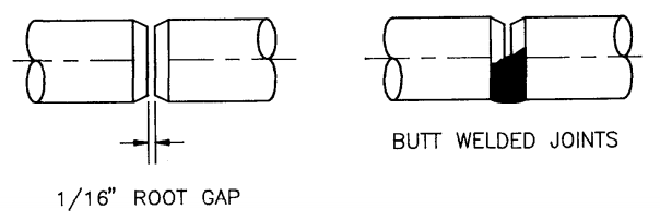
Butt Weld Joint
A butt weld joint is made by welding the beveled ends of the two pipes. Beveled ends (BE) indicate that the ends of the pipe are not plain end, but rather cut at angle to form tapered edge.
Butt welding is the most common method of joining the pipes. Material costs are low, as no external components are required to attach with, but the labor costs are high due to the need of expert and qualified welders & fitters. Leakage integrity is extremely good, the internal surface of a butt welded piping system is smooth and continuous which cause to low pressure drop.
In preparation of the welding process, a welder will separate the two pipes with a small gap of 1.5 mm, this gap is known as root gap. During the welding process, the two ends are drawn together and the gap disappears.
If the two pipe pieces of 2 meters each are welded together in this manner, the result would be a total length of 4 meters. However, sometimes a back-up ring is used for critical lines to prevent the formation of weld icicles inside the pipe and also to lower the cost of the project.
But, but the back-up rings create internal crevices, which can entrap the corrosive products. The back-up ring creates a gap of 3 mm between the two pipe pieces. In this method, the ring does not allow the ends of the pipe to be drawn together and keeps them separated by the proper gap. If two pipes of length 3 meters each are welded together using a back-up ring, then the result would be a total length of 6 meters and 3 mm. This gap should be shown while dimensioning the pipe.
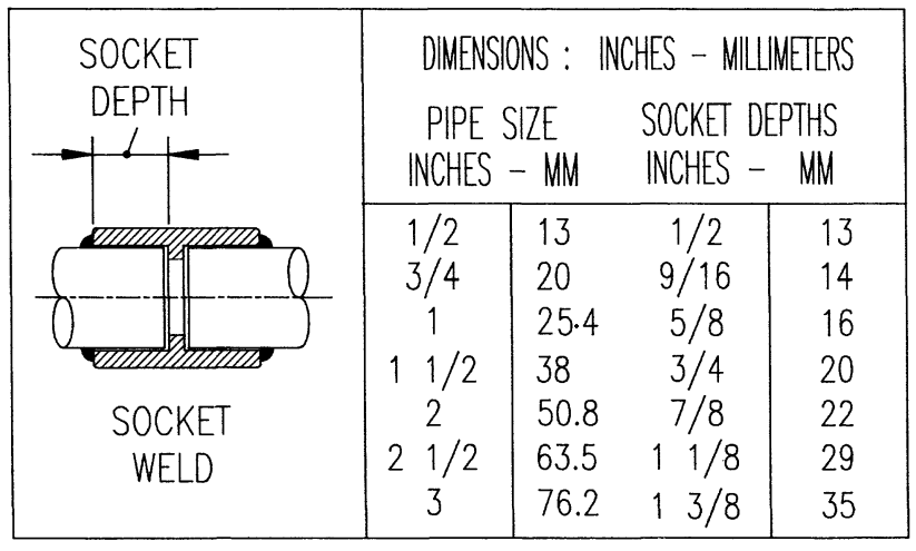
Socket Weld Joint
A socket weld joint is a good option when the high leakage integrity and great structural strength are important design considerations for smaller pipe sizes (mainly up to 2″ NPS).
Construction costs are comparatively lower than butt-welded joints due to the less skilled welders are required, ease of pipe allignment, and elimination of special machining unlike the butt weld end preparation.
The internal crevices left in socket welded piping systems make them less suitable for corrosive fluid or radioactive applications, it also cause to fluid stagnation. Fatigue resistance is lower unlike the butt welded joints due to the use of fillet welds.
Inside the socket weld fittings, there is a collar that prevents the pipe to go deep inside. The socket length will vary per the pipe size. The data can be found in ASME B16.11.
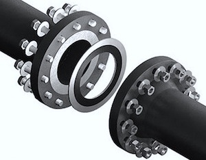
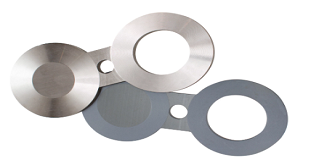
Flanged Joints
The number of flanged joint connections in a piping system is normally determined by the maintenance and erection considerations. The flanged joints are required for the insertion of blanks to isolate the system during shutdown maintenance and hydro testing of the piping system. If the flanges of different ratings are bolted together, the rating of that flanged joint must not exceed the lower-rated flange. The selection of flanges is a broad topic itself.
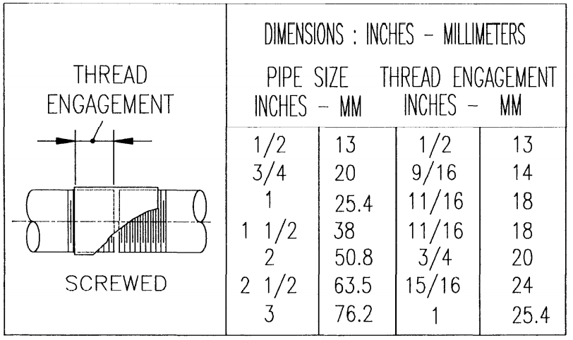
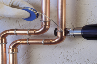
Threaded Joints
The economics and safety restrict the use of threaded piping to small pipe sizes, up to NPS 2″ (DN 50) for most services. The threading of the pipe with a wall thickness less than the thickness provided in the ASME B36.10M standard is not allowed in accordance with code.
The use of threaded joints should be avoided where corrosion, erosion, or cyclic loading may occur. All pipe threads on piping components must be prepared in accordance with ASME B1.20.1.
Seal welding of threaded joints is recommended for all the services except for Category D fluid (non-toxic fluid) services. Threaded joints do not require to be seal welded if the joint is made for instrument connections or for piping components that expect cyclic removal for maintenance. Similarly, the seal welding is not required for plugs and caps used in drain and vent valves, and for union ring threads as well.
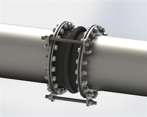
Expansion Joints
The expansion joint is more commonly used in the piping system used for refinery heaters or steam generators (means hight temperature lines). The expansion joints are the last option for the piping system, as we are required to try other ways to handle the expansion and contraction of the line (like by providing an expansion loop). They are also used in the case of tank settlement.
Expansion joints are prohibited for use in hazardous or toxic services and under cyclic conditions. Expansion joints are not typically recommended to use in process applications. Although, if they are used, considerations must be addressed to the tightness of the expanded joint when subjected to vibration, differential expansion, or contraction due to temperature cycling or external mechanical loads.
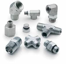
Flared, Flareless, and Compression Joints
The use of flared, flareless, or compression type joints is considered for tubing connections, as it may be needed for instruments or other similar devices, within the limitations of relevant component standards or specifications.
In the absence of such standards or specifications, the sufficiency of the fitting should consider the following:
- The design pressure must fulfill the requirements of the Code
- A proper quantity of the type & size of the fitting to be used should fulfill the successful performance tests to find the safety of the joint under simulated or similar service conditions.
- Fittings should not be used in services that exceed the manufacturer’s maximum pressure & temperature limits and their recommendation.
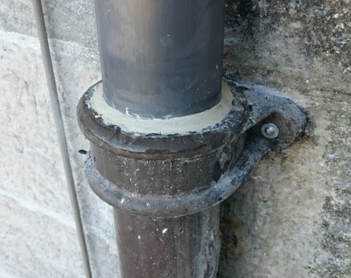
Caulked Joints
The term caulked joints apply to joints of the bell-and-spigot type which is permitted only for Category D (non-flammable or non- toxic) like water service and to a temperature up to 93°C. It must be used within the pressure-temperature limits of the pipe to that they are applied. The provisions must be executed to prevent disengagement of the joints at bends and dead ends and to support lateral reactions produced by branch connections.
Brazed and Soldered Joints
Fillet-brazed or fillet-soldered joints may not be used in process piping, but the use of soldered and brazed socket type joints is allowed in non-flammable or non-toxic services. The melting point of brazing alloys should be acknowledged where possible exposure to fire is involved for that piping system.
Other Proprietary Joints
Coupling type, mechanical-gland type, and other exclusive joints are available and may be considered for use. The design should be verified according to the methods provided in ASME B31.3 for special fittings, which should cover the performance testing of a prototype joint to verify the safety of the joint under simulated service situations.
You may also like to read
Pump Cavitation: Causes, Effects, & Preventive Actions
Types of Pumps: Centrifugal Pump & Positive Displacement Pump
Reinforcement Pad Calculation for Branch Connection
Miter Elbow or Miter Bend Design Calculations
Pipe Wall Thickness Calculation For External Pressure or Vacuum
References
Piping Hand Book by Mohinder L. Nayyar, P.E.
Piping and Pipe Line Engineering By George A. Antaki

Dear Rehan,
In my point you should not include expansion joint in the category of pipe joining process.
Pipie joining means either by welding, flanged or threaded. Expansion joint is an in line item used where the line experience thermal stresses, pressure thrust to reduce the nozzle loads mainly.
Hi
First of all thank you for your great website, Dear Rehan, I think this picture (Caulked Joints) is not about the Connection between Bell and Spigot, did I get it right?
Regards
Rahim Maleki
Sep.23.2021
Hello Rahim,
Thanks for your read,
This picture belongs to Bell and Spigot Joint only. I think You are misinterpreting due to the clamp attached to it.
Excellent information, well done for creating this valuable resourse.