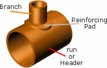
A reinforcement pad or RF pad is used to strengthen the fabricated or welded pipe branch connection joints. Standard branch fittings such as Tee and Olets Fittings are generally used to take out the branch from the header or runner pipe, but these standard fittings are not easily available and economical for a large size range.
In such cases, we are required to make the fabricated branch connection (stub-in or stub-on). Fabricated branch connections are not as strong as the standard branch fittings, so to recover this strength gap between the standard branch fittings and fabricated branch joints, it is required to use the reinforcement pad or RF pad. But, it is not compulsory that all the fabricated branch connection joints are required a reinforcement pad.
In this article, we will learn, how to decide whether the reinforcement pad is required or not for the size combination of the header and branch pipe? What should be the thickness and dimensions of the RF pad or reinforcement Pad?
Table of Contents
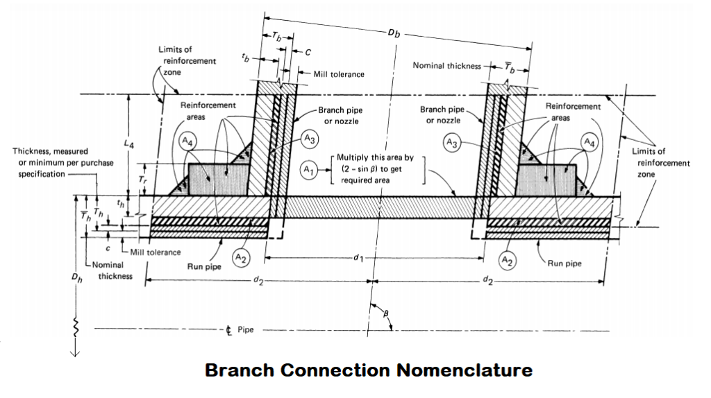
Fabricated Branch Connection Nomenclature
A pipe having a fabricated or welded branch connection is weakened by cutting out some area from the header pipe to fit the branch pipe onto it.
Unless the wall thickness of the pipe is sufficient to sustain the pressure, it is necessary to provide added reinforcement pad. The amount of reinforcement or strength required to sustain the pressure is determined in accordance with para. 304.3.3 or 304.3.4 of ASME B31.3. Let’s see the nomenclature as per para 304.3.3 below-
Where,
A1 = Area removed from the header or run pipe
A2 = Extrathickness available in the header pipe
A3 = Extrathickness available in the branch pipe
A4 = Area of RF Pad & area of welding
L4 = Height of the reinforcement zone
β = Angle between axes of the branch and header or run pipe
d1 = Effective length removed from the run or header pipe
d2 = Half-width of the reinforcement zone
Db = Outside diameter of branch pipe
Dh = Outside diameter of run or header pipe

Th = Tb = Thickness after deducting mill tolerance from nominal pipe thickness or ordering thickness of run and branch pipe respectively
th = tb = Calculated pipe thickness as per the equation of para. 304.1 of ASME B31.3 for run and branch respectively.
C = Corrosion allowance
Tr = Minimum thickness of reinforcement pad
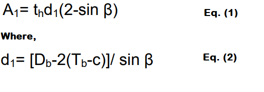
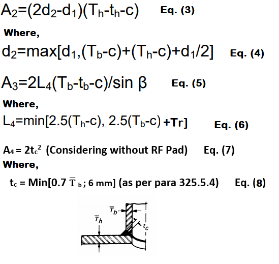
Formulas used for Reinforcement Pad Calculation
To decide, whether the reinforcement pad or RF pad is required or not, the following formulas are used-
Inputs Required for RF Pad Calculation
Run pipe material- A672Gr.B
Branch pipe material- A106 Gr.B
Run pipe type- Welded
Branch pipe type- Seamless
Dh– 20″ = 508 mm
Db– 14″ = 355.6 mm
β- 90°
Design Pressure- 503 Psi
Design Temperature- 400°C
Mill tolerance for run or header pipe- ±0.3 mm
Mill tolerance for branch pipe- ±12.5% mm
Corrosion allowances for run pipe (C)- 3 mm
Corrosion allowances for branch pipe (C)- 3 mm
Reinforcement Pad Calculation Steps
Follow the below steps to get the result:
Step 1: Calculate the Run and Branch Pipe Thicknesses
I have already written an article on Pipe Thickness Calculation. Click here to see the calculation steps
After following the steps mentioned in above articles, we have got the following value
th = 11.83 mm
tb = 7.06 mm
Now, we can get Th & Tb from the above value
Th = 16-0.3 = 15.70 mm
Tb = 15.09×0.875 = 13.20 mm
Step 2: Find d1
Put the required values in equation (2) of formulas section
d1 = [355.6 – 2(13.20 – 3)] / Sin 90° = 335.20 mm
Step 3: Calculate A1
Put the required values in equation (1)
A1 = 11.83 × 335.20 (2 – Sin 90°) = 3965.41 mm2
Step 4: Find d2
Put the required values in equation (4)
d2 = Max[335.20 ; {(13.20-3)+(15.70-3)+(335.20/2)}]
= Max[335.20 ; 190.50]
d2 = 335.20 mm
Step 5: Now, Calculate A2
Put the required values in equation (3)
A2 = [(2×335.20)-335.20)(15.70-11.83-3)]= 291.62 mm2
Step 6: Find L4
Put the required values in equation (6)
L4 = Min[{2.5(15.70-3)} ; {2.5(13.20-3)+0}] (Considering Tr = 0)
= Min[31.75 ; 25.5]
L4 = 25.50 mm
Step 7: Now, Calculate A3
Put the required values in equation (5)
A3 = 2×25.5(13.20-7.06-3)/Sin90° = 160.14 mm2
Step 8: Find tc
Put the required values in equation (8)
tc = Min [0.7×15.09 ; 6]
= Min [10.56 ; 6]
tc = 6 mm
Step 9: Now, Calculate A4
Put the required values in equation (7)
A4 = 2×62 = 72 mm2
Step 10: Check if A1≥A2+A3+A4
Add A2+A3+A4 = 291.62+160.14+72 = 523.76 mm2 and we have A1 = 3965.41 mm2
Now, we can see A1>A2+A3+A4
Therefore, it is clear that we need to provide an RF pad to strengthen the joint.
Important Note:
If A1<A2+A3+A4 then RF Pad or Reinforcement Pad is not needed to provide
Reinforcement Pad Thickness Calculation
In most cases, RF Pad thickness is the same as the header or run pipe thickness, but we need to cross-check whether the reinforcement pad can be made from the run pipe.
So, Let’s consider RF Pad is taken from the header with the outer diameter (Dr ) = 2Db = 711.20 mm and thickness (Tr ) = Th = 15.70 mm
Note: RF Pad diameter is taken as two times the outer diameter of the branch pipe.
Step 1: Calculate L4 again considering RF Pad is already provided
L4 = Min[{2.5(Th-C)} ; {2.5(Tb-C)+Tr}]
L4 = Min[{2.5(15.70-3)} ; {2.5(13.20-3)+15.70}] = 291.62 mm2
= Min[31.75 ; 41.12]
L4 = 31.75 mm
Step 2: Now, Calculate A3 considering RF Pad
A3 = 2×L4 (Tb-tb-C)
= 2×31.75 (13.20-7.06-3)
A3= 199.39 mm2
Step 3: Calculate A4 considering RF Pad
A4 = [{2×d1 – (Db / Sinβ)}(Th)+2tc2]
= [{2×335.20 – (355.6/sin90°)}(15.70)+(2×62)]
A4= 5014.36 mm2
Step 4: Now Check if A1<A2+A3+A4
We have from the old calculation,
A1 = 3965.41 mm2
A2 = 291.62 mm2
We know from the latest calculation,
A3= 199.39 mm2
A4= 5014.36 mm2
Now, let’s check the condition below
IF A1<A2+A3+A4 = 3965.41<291.62+199.39+5014.36
3965.41< 5505.37
We can see from the above calculation A1<A2+A3+A4
The above result ensures that a reinforcement pad can be made from the header or run pipe for our case.
If still A1≥A2+A3+A4 then we need to use a higher thickness pipe for reinforcement pad or RF pad.
We need to continue the calculation with the increased thickness of the pipe until the condition “A1<A2+A3+A4” met.
I hope, now you can easily do the calculation for Reinforcement Pad. Do practice once or twice with other examples to clear all the doubts. Thanks for reading.
You may also like to read
Pipe Wall Thickness Calculation For External Pressure or Vacuum
A Presentation on Heat Exchanger
Some Important Piping Codes and Standards
Pipe Welding Positions: 1G, 2G, 5G, and 6G
Hydrotest Procedure for Piping system
Pipe Rack Design and Calculations
Image Source
ASME B31.3
http://www.copcosa.com/soft/mecheng07/rob3.htm


THIS RF PAD CALCULATION IS REALLY VERY HELPFUL FOR ME, IT HAS CLEARED MY DOUBT. THANK YOU.
Thanks, Ravi
Your article is very simple.
Thanks for the read Anthony
hello dear Rehan
Thank you for sharing this article.
Please help me about two tiny problems!
1- Is the parameters t_h and t_b used in above formulas include c (corrosion and mechanical allowances)? i.e. t_h=PD/(SEW+PY)+c? (the 4″ pipe in my case include a 2mm depth groove and 0mm corrosion allowance)
sincerely.
Hello Mr. Mehrshad,
Thanks for your reading.
No, t_h does not include corrosion and mechanical allowances. The below equation shall be used:
t_h=PD/(SEW+PY)
in above case 14″ th=6.82 with E,W=1and y=0.4 … But tb you have got 7.06mm
s=12912psi
Can we make RF pad in split form?
yes you can
Sir, calculated thickness of branch tb=7.06mm is not correct, kindly cross check it once
how to obtain tb = 7.06 mm? fromclause 304.1.1 t=PD/(2SEW+2PY) … E,W=1 and y=0.4 ? could you please clarify
Hello, Great article!
I have a question about calculating the RF pad thickness. In step 3, when calculating A4, do you use the Header thickness (Th) or is this the RF pad thickness (Tr)? I understand that in this example Th=Tr however, if I put the Tr value at 0 it still says A1<A2+A3+A4 which contradicts the theory that an RF pad is required per the previous equation?
Thanks in advance.
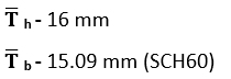
How we get Th and Tb values as 16 and 15.09mm respectively??
Please tell the stress and Y value in this case